Power device of milling and planing machine

A power device and milling machine technology, which is applied in roads, road repairs, roads, etc., can solve the problems of high manufacturing cost and large engine power consumption, and achieve the effects of lower manufacturing cost, lower price, and lower use cost

Inactive Publication Date: 2015-05-27
GUANGXI LIUGONG MASCH CO LTD
View PDF6 Cites 0 Cited by
  • Summary
  • Abstract
  • Description
  • Claims
  • Application Information

AI Technical Summary

Problems solved by technology

[0006] The technical problem to be solved by the present invention is to provide a milling machine power device, which can solve the problems of large power consumption and high manufacturing cost of the existing road milling machine engine

Method used


Image

  • Power device of milling and planing machine
  • Power device of milling and planing machine

Examples


Embodiment Construction

[0015] The present invention will be described in further detail below in conjunction with accompanying drawing embodiment:

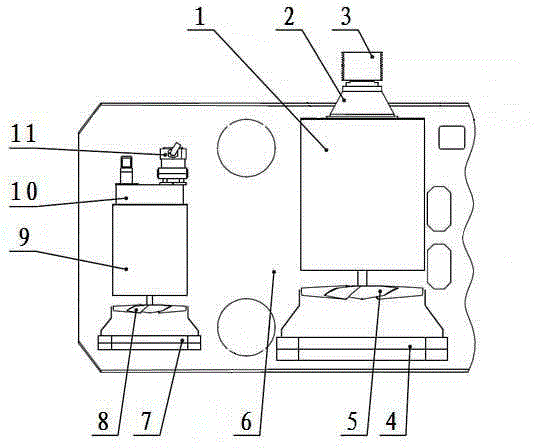
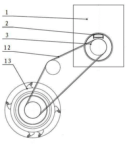
[0016] Such as figure 1 , figure 2 The power unit of the milling machine shown includes a milling drum 13 installed on the lower part of the frame 6 and a hydraulic pump 11 installed on the output shaft of the transfer case 10. The hydraulic pump 11 communicates with the hydraulic motor driving the walking and auxiliary working devices through the hydraulic pipe. connect. The input shaft of the milling drum 13 is sleeved with a belt pulley, the belt pulley is connected with the belt pulley 3 through the belt 12, and the belt pulley 3 is installed on the output shaft at one end of the first power machine through the clutch 2. The first and second power machines in the present embodiment are respectively The first motor 1 and the second motor 9, the first motor 1 and the second motor 9 are respectively fixed on the frame 6 by bolts; the output shaft at...


PUM


Abstract

The invention discloses a power device of a milling and planing machine, relating to the technical field of construction machinery manufacturing. The power device comprises a clutch connected with a milling and planing drum through transmission of a belt, and a hydraulic pump arranged on a transfer case output shaft, wherein the clutch is arranged on an output shaft at one end of a first power machine, a first fan is arranged on an output shaft at the other end of the first power machine, a first heat radiator is arranged close to the first fan, a transfer case is arranged on an output shaft at one end of a second power machine, a second fan is arranged on an output shaft at the other end of the second power machine, and a second heat radiator is arranged close to the second fan. Compared with the prior art, the power device has the advantage that the problems of large power consumption and high in manufacture cost of an engine of an existing road milling and planing machine can be solved.

Description

technical field [0001] The invention relates to the technical field of engineering machinery manufacturing, in particular to a power device for a road milling machine. Background technique [0002] Pavement milling machine is one of the main types of asphalt pavement maintenance construction machinery, mainly used for clearing sacks, oil waves, reticulations, ruts, etc. on asphalt concrete surfaces such as highways and urban roads. There is a power unit of a road milling machine with a milling width greater than 2 meters equipped with a high-power engine; this milling machine power unit includes an engine mounted on a frame, and the power output of the engine passes through the transfer case After that, it is divided into two power outputs, one power output is connected with a clutch, and the clutch is connected with the milling drum through a belt drive; the other power output of the transfer case is connected with a hydraulic pump, and the hydraulic pump is connected to th...

Claims


Application Information

Patent Timeline
Patent Type & Authority Patents(China)
IPC IPC(8): E01C23/088
Inventor 莫德志
Owner GUANGXI LIUGONG MASCH CO LTD
Why Eureka
Try Eureka