Testing device and testing method of anchor-tension type retaining wall model

A model test device and retaining wall technology, which is applied in the fields of railway engineering, geotechnical engineering, and road engineering, can solve problems such as different force characteristics, achieve convenient transportation, easy processing, and improve work efficiency

Inactive Publication Date: 2013-08-07
SHANDONG UNIV
View PDF6 Cites 39 Cited by
  • Summary
  • Abstract
  • Description
  • Claims
  • Application Information

AI Technical Summary

Problems solved by technology

However, because its mechanical characteristics are significantly different from those of ordinary retaining walls, how to establish a reasonable mechanical calculation model has become a hot issue in engineering circles

Method used


Image

  • Testing device and testing method of anchor-tension type retaining wall model
  • Testing device and testing method of anchor-tension type retaining wall model
  • Testing device and testing method of anchor-tension type retaining wall model

Examples


Embodiment 1

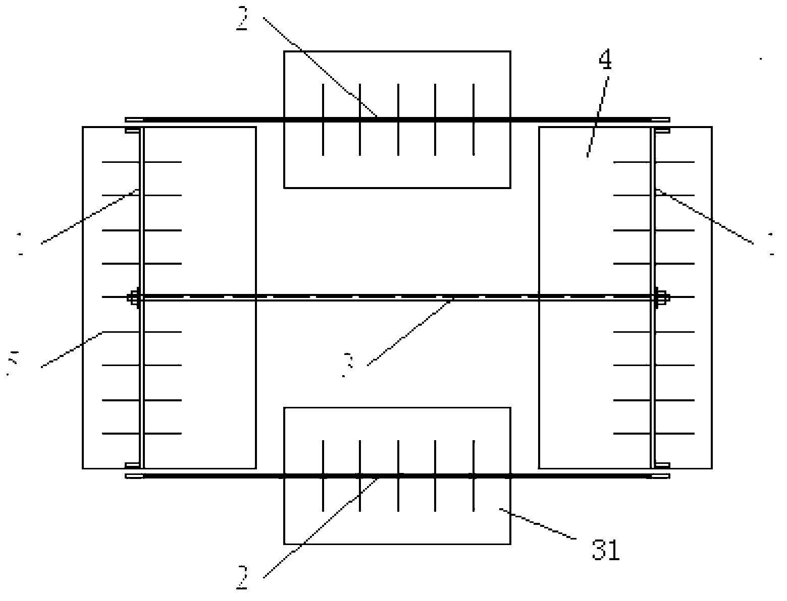
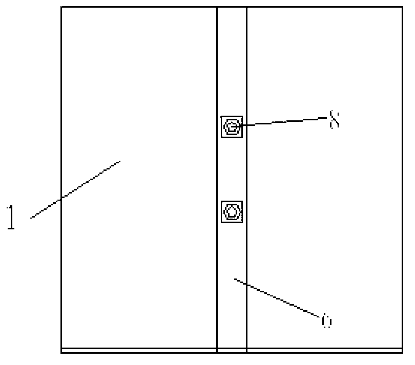
[0049] An anchor pull type retaining wall model test device, combined Figure 1 to Figure 7 , Including the test slot 24, the main bearing surface cantilever retaining wall, the auxiliary bearing surface cantilever retaining wall, the loading system, the test system; the main bearing surface cantilever retaining wall, the auxiliary bearing surface cantilever retaining wall are set in the test slot 24 Inside, the main bearing surface cantilever retaining wall includes a main bearing surface vertical steel plate 1 and a first horizontal steel plate 4 connected, and the main bearing surface vertical steel plate 1 is welded to the first horizontal steel plate 4; The force surface cantilever retaining wall includes the auxiliary force surface vertical steel plate 2 and the second horizontal steel plate 31 connected, the main force surface vertical steel plate 2 and the second horizontal steel plate 31 are welded; the main force surface vertical steel plate 1 The first anchor rod hol...

Embodiment 2

[0079] Among them, the vertical steel plate 1 of the main bearing surface cantilever retaining wall has a thickness of 20mm, a length of 2000mm, and a width of 2000mm. The horizontal steel plate 4 is 30mm thick, 2000mm long and 90mm wide. The height of the auxiliary bearing surface cantilever retaining wall is the same as the main bearing surface cantilever retaining wall. The vertical steel plate 2 of the auxiliary bearing surface cantilever retaining wall is 10mm thick, 2000mm long and 2000mm wide.

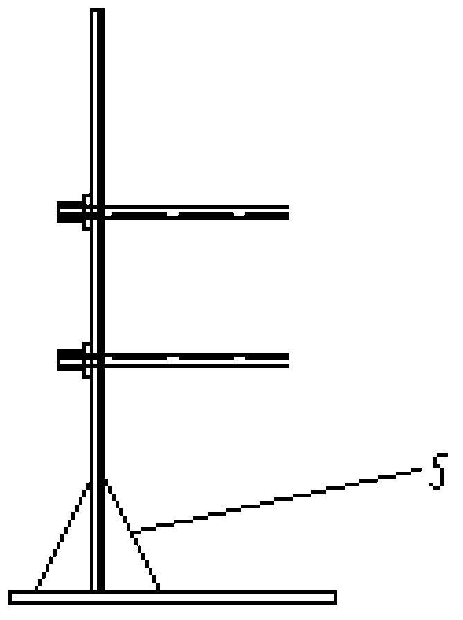
[0080] Reinforced ribs 5 are arranged between the vertical steel plates and horizontal steel plates of the main bearing surface cantilever retaining wall and the auxiliary bearing surface retaining wall. The thickness of the reinforced rib 5 is 30mm, the height is 400mm, the bottom length is 200mm, and the uniform spacing is 200mm. The reinforcing rib 5 avoids welding deformation when the vertical steel plate and the horizontal steel plate are welded; the vertical steel plate 1 of ...

Embodiment 3

[0099] The main bearing surface cantilever retaining wall and the auxiliary bearing surface cantilever retaining wall are made of Q235 steel plate, of which the vertical steel plate 1 of the main bearing surface cantilever retaining wall has a thickness of 20mm, a length of 2000mm and a width of 2000mm. The horizontal steel plate 4 is 30mm thick, 2000mm long and 90mm wide. The height of the auxiliary bearing surface cantilever retaining wall is the same as the main bearing surface cantilever retaining wall. The vertical steel plate 2 of the auxiliary bearing surface cantilever retaining wall is 10mm thick, 2000mm long and 2000mm wide.

[0100] Reinforced ribs 5 are arranged between the vertical steel plates and horizontal steel plates of the main bearing surface cantilever retaining wall and the auxiliary bearing surface retaining wall. The thickness of the reinforced rib 5 is 30mm, the height is 400mm, the bottom length is 200mm, and the uniform spacing is 200mm. The reinforcing...


PUM


Abstract

The invention discloses a testing device and a testing device of an anchor-tension type retaining wall model. The testing device of the anchor-tension type retaining wall model comprises a testing groove, a main force-bearing surface cantilever retaining wall, an auxiliary force-bearing surface cantilever retaining wall, a loading system and a testing system. The main force-bearing surface cantilever retaining wall and the auxiliary force-bearing surface cantilever retaining wall are arranged inside the testing groove, the main force-bearing surface cantilever retaining wall comprises a main force-bearing surface vertical steel plate and a first horizontal steel plate which are connected with each other, the auxiliary force-bearing surface cantilever retaining wall comprises an auxiliary force-bearing surface vertical steel plate and a second horizontal steel plate which are connected with each other, the main force-bearing surface vertical steel plate is provided with a first rock bolt through hole, and the auxiliary force-bearing surface vertical steel plate is provided with a second rock bolt through hole. The loading system comprises a vertical loading structure and a prestress loading structure, the lower portion of the vertical loading structure is connected with the floor, the upper portion of the vertical loading structure is connected with the filling in a contact mode, and the prestress loading structure is connected with both sides of the main force-bearing surface cantilever retaining wall. The testing device of the anchor-tension type retaining wall model is convenient to mount and dismount, reusable and capable of reducing the cost and improving the working efficiency.

Description

Technical field: [0001] The invention relates to the technical fields of road engineering, railway engineering, and geotechnical engineering, in particular to an anchor-pull type retaining wall model test device and test method. Background technique: [0002] With the increasing shortage of arable land resources in our country, land resources in the process of highway construction are becoming more and more precious, and the technology of replacing high embankment slopes with retaining walls has attracted extensive attention from the engineering community. In order to improve the anti-tilting and anti-sliding stability of the retaining wall, the reinforced retaining wall structure has become a newly developed retaining wall structure with good application effects. However, because its force characteristics are significantly different from ordinary retaining walls, how to establish a reasonable mechanical calculation model has become a hot issue in the engineering community. Mode...

Claims


Application Information

Patent Timeline
Patent Type & Authority Applications(China)
IPC IPC(8): E02D33/00
Inventor 张宏博李英勇宋修广薛志超郑立志吴建清臧亚囡江健宏
Owner SHANDONG UNIV
Why Eureka
Try Eureka