Automatic drill pipe assembly and disassembly mechanism of trenchless horizontal directional drilling machine

A horizontal directional drilling rig, automatic loading and unloading technology, applied in the direction of drill pipe, drill pipe, drilling equipment, etc., can solve the problems of high construction cost, unreliable work, collapse of drilled holes, etc., to achieve fast automatic loading and unloading, stable operation Reliable and labor cost-reducing effects

Active Publication Date: 2015-04-22
江苏谷登重型机械科技股份有限公司
View PDF8 Cites 1 Cited by
  • Summary
  • Abstract
  • Description
  • Claims
  • Application Information

AI Technical Summary

Problems solved by technology

Its actions are numerous and complicated, and misoperation, unreliable work, drill pipe slipping, failures, etc. often occur, and may even cause major accidents such as collapse of drilled holes and buried drills.
The existing automatic loading and unloading mechanism cannot guarantee the accuracy, coordination, reliability and stability of each action at all, and the efficiency is extremely low, and the construction cost remains high. At present, some construction units even prefer to use the most primitive construction method ——Manual loading and unloading, and unwilling to use the existing automatic loading and unloading mechanism for construction, which greatly increases the labor intensity of construction personnel
At the same time, the design of the existing automatic loading and unloading rod mechanism itself is bulky and complicated, the production and processing of the product are complicated, and the adaptability is poor, which cannot meet the needs of modern production and processing.

Method used


Image

  • Automatic drill pipe assembly and disassembly mechanism of trenchless horizontal directional drilling machine
  • Automatic drill pipe assembly and disassembly mechanism of trenchless horizontal directional drilling machine
  • Automatic drill pipe assembly and disassembly mechanism of trenchless horizontal directional drilling machine

Examples


Embodiment Construction

[0014] The specific content of the present invention will be described in detail below in conjunction with the accompanying drawings and specific embodiments.

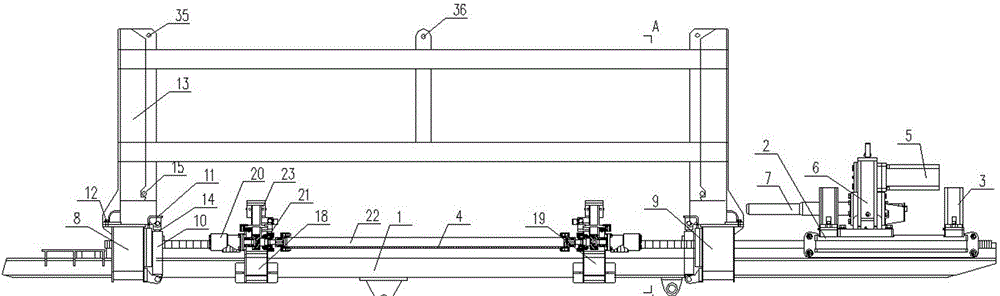
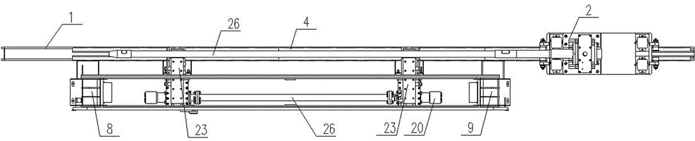
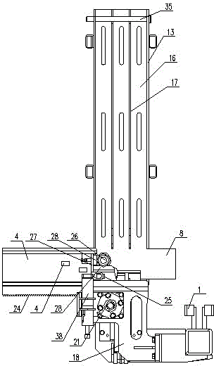
[0015] Such as figure 1 , figure 2 , image 3 , Figure 4 As shown, the non-excavation horizontal directional drilling machine automatically loads and unloads the drilling rod mechanism, including: a beam 1 and a power head device 2 slidingly arranged on the beam 1, and the lower end of the power head device 2 is provided with a power head push-pull motor 3 and a push-pull gear. The push-pull rack 4 cooperating with the push-pull gear is arranged on the beam 1, the upper end of the power head device 2 is provided with a power head rotation motor 5 and a power head rotation gearbox 6, and the power head rotation motor 5 The rotary gear box 6 of the power head is connected with the variable diameter 7, and the left drill box fixing seat 8 and the right drilling box fixing seat 9 are fixedly arranged on the said beam ...


PUM


Abstract

The invention discloses an automatic drill pipe assembly and disassembly mechanism of a trenchless horizontal directional drilling machine. The automatic drill pipe assembly and disassembly mechanism is convenient, quick and reliable to use and comprises a beam and a power head device which is slidingly arranged on the beam, a left drill pipe box fixing base and a right drill pipe box fixing base are fixed on the beam, jacking oil cylinders are fixedly arranged on the inner side of the left drill pipe box fixing base and the inner side of the right drill pipe box fixing base respectively, jacking plates are arranged on piston rods of jacking oil cylinders, drill pipe boxes are fixedly arranged on the left drill pipe box fixing base and the right drill pipe box fixing base through bolts, a left supporting base and a right supporting base are fixedly arranged on the beam between the left drill pipe box fixing base and the right drill pipe box fixing base respectively, upper pipe supporting bases are arranged on the left supporting base and the right supporting base respectively, supporting steps which are matched with drill pipes are arranged at front ends of upper pipe supporting bases, and magnet sheets are arranged at upper ends of supporting steps and on side faces of supporting steps.

Description

technical field [0001] The invention relates to a non-excavation horizontal directional drilling machine, in particular to an automatic loading and unloading drill rod mechanism of the non-excavation horizontal directional drilling machine. Background technique [0002] During the construction process of trenchless horizontal directional drilling rigs, automatic rod loading and unloading mechanisms are generally used. The existing automatic rod loading and unloading mechanisms are mainly composed of: drill pipe box, drill pipe grabbing mechanism, drill pipe lifting device, drill pipe It is composed of a translation device and a drill pipe unscrewing mechanism. Its actions are numerous and complicated, and misoperation, unreliable work, drill pipe slipping, failures and other situations often occur, and may even cause major accidents such as collapse of drilled holes and buried drills. The existing automatic loading and unloading mechanism cannot guarantee the accuracy, coo...

Claims


Application Information

Patent Timeline
Patent Type & Authority Patents(China)
IPC IPC(8): E21B17/00
Inventor 陈凤钢陆猛王斌斌訚耀保
Owner 江苏谷登重型机械科技股份有限公司
Why Eureka
Try Eureka