Check patentability & draft patents in minutes with Patsnap Eureka AI!

A catenary wire wear detection device

A detection device and catenary technology, applied in the detection field, can solve the problems of measurement accuracy limitation and high detection cost, and achieve the effects of convenient operation, reliable work, high detection efficiency and detection accuracy

Inactive Publication Date: 2016-03-30
HEBEI UNIVERSITY OF SCIENCE AND TECHNOLOGY
View PDF4 Cites 0 Cited by
  • Summary
  • Abstract
  • Description
  • Claims
  • Application Information

AI Technical Summary

Problems solved by technology

These detection methods are easy to operate, safe and convenient, but the disadvantages are that the detection cost is high and the measurement accuracy is limited.

Method used


Image

  • A catenary wire wear detection device
  • A catenary wire wear detection device
  • A catenary wire wear detection device

Examples


Embodiment Construction

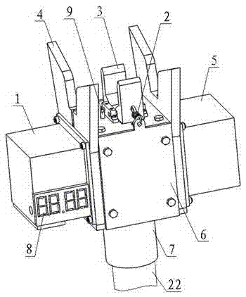
[0028] like figure 1 As shown, the cross-section of the catenary conductor to be detected is an irregular circle, and the notches on both sides of the upper part are used for sling clamping. The worn part is the lower part of the conductor, when the catenary conductor is excessively worn (such as figure 2 As shown), the cross-section of the wire is too small will cause the current density to flow too high, which will cause an accident.

[0029] see Figure 3 ~ Figure 11 , the device includes a measurement control system, a clamping clamp return spring 2, a clamping clamp 3, a guide plate 4, a housing 6, an insulating rod joint 7, a display 8, a guide block 10, a differential transformer return spring 11, a detection cam 12, Lifting cam 13, drive shaft 14, lifting block 15, differential transformer 16, guide column 17, sleeve 19, bearing 20, stepper motor 21, insulating rod 22.

[0030] The bottom of shell 6 is provided with 4.5 meters long insulating rod 22, to facilitate ...


PUM


Abstract

A contact wire abrasion detecting device comprises a shell, clamp pliers, a stepping motor, a lifting block, a differential transformer and a horizontal drive shaft, wherein the lifting block, the differential transformer and the horizontal drive shaft are located in the shell. Lowers ends of two L-shaped plier arms of the clamp pliers are hinged with the shell. The lifting block is slidably connected with the shell through a vertical guide column and provided with two protrusions corresponding to the two plier arms. The differential transformer is slidably connected with the lifting block through a vertical slideway. A detecting contact of the differential transformer corresponds to a contact wire in a jaw of the clamp pliers. The drive shaft is connected with the shell through a bearing and provided with a detecting cam corresponding to the differential transformer and a lifting cam corresponding to the lifting block. The stepping motor is fixedly connected with the shell. An output shaft of the stepping motor is in butt joint with the drive shaft. Output of the differential transformer is connected with a measuring control system. The contact wire abrasion detecting device is convenient to operate, reliable in operation, high in detecting efficiency and precision, capable of satisfying the requirements for electric railway abrasion detection and the like.

Description

technical field [0001] The invention relates to an intelligent wire wear detection device suitable for an electrified railway catenary, and belongs to the technical field of detection. Background technique [0002] The catenary is a special form of transmission line erected along the railway line, and its contact line (see figure 1 ) provides continuous and reliable electric energy for the locomotive through direct contact with the pantograph of the electric locomotive. When the lower part of the catenary conductor is excessively worn (see figure 2 ), it cannot supply power normally. To ensure the reliable operation of electric locomotives, it is necessary to regularly measure the wear of contact wires. [0003] The traditional measurement method is to connect several insulating rods that look like "fishing rods" and hang them directly on the 27KV high-voltage wire (contact wire), let it hang down naturally, and then use a ruler to measure and convert to get the catenary...

Claims


Application Information

Patent Timeline
Patent Type & Authority Patents(China)
IPC IPC(8): G01B7/02
Inventor 张弛石建玲魏泽鼎
Owner HEBEI UNIVERSITY OF SCIENCE AND TECHNOLOGY
Features
  • R&D
  • Intellectual Property
  • Life Sciences
  • Materials
  • Tech Scout
  • Unparalleled Data Quality
  • Higher Quality Content
  • 60% Fewer Hallucinations
Learn More