Loading device used in road seam filling material low-temperature performance test

A technology for loading devices and filling materials, which is applied in the direction of measuring devices, analyzing materials, and using stable tension/pressure to test the strength of materials, etc. It can solve the problems of slow installation speed of test pieces and affect test accuracy, and shorten the installation time , high test efficiency and energy saving effect

Active Publication Date: 2013-08-07
HARBIN INST OF TECH
View PDF9 Cites 9 Cited by
  • Summary
  • Abstract
  • Description
  • Claims
  • Application Information

AI Technical Summary

Problems solved by technology

[0003] The purpose of the present invention is to solve the problem that the existing loading device has a relatively slow installation speed of the test piece, adopts a slide way for loading, has a certain resistance, and affects the test accuracy, and further provides a low-temperature performance test for road joint filling materials. loading device

Method used


Image

  • Loading device used in road seam filling material low-temperature performance test
  • Loading device used in road seam filling material low-temperature performance test
  • Loading device used in road seam filling material low-temperature performance test

Examples


specific Embodiment approach 1

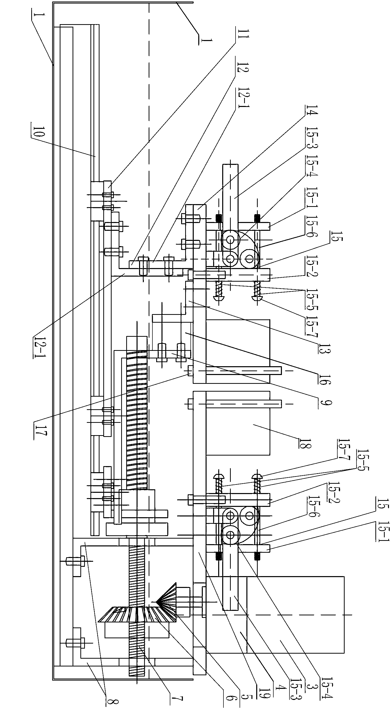
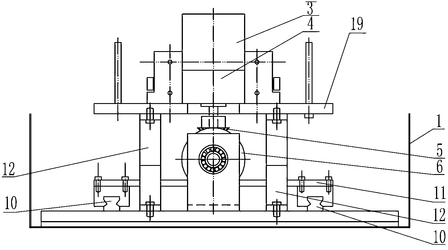
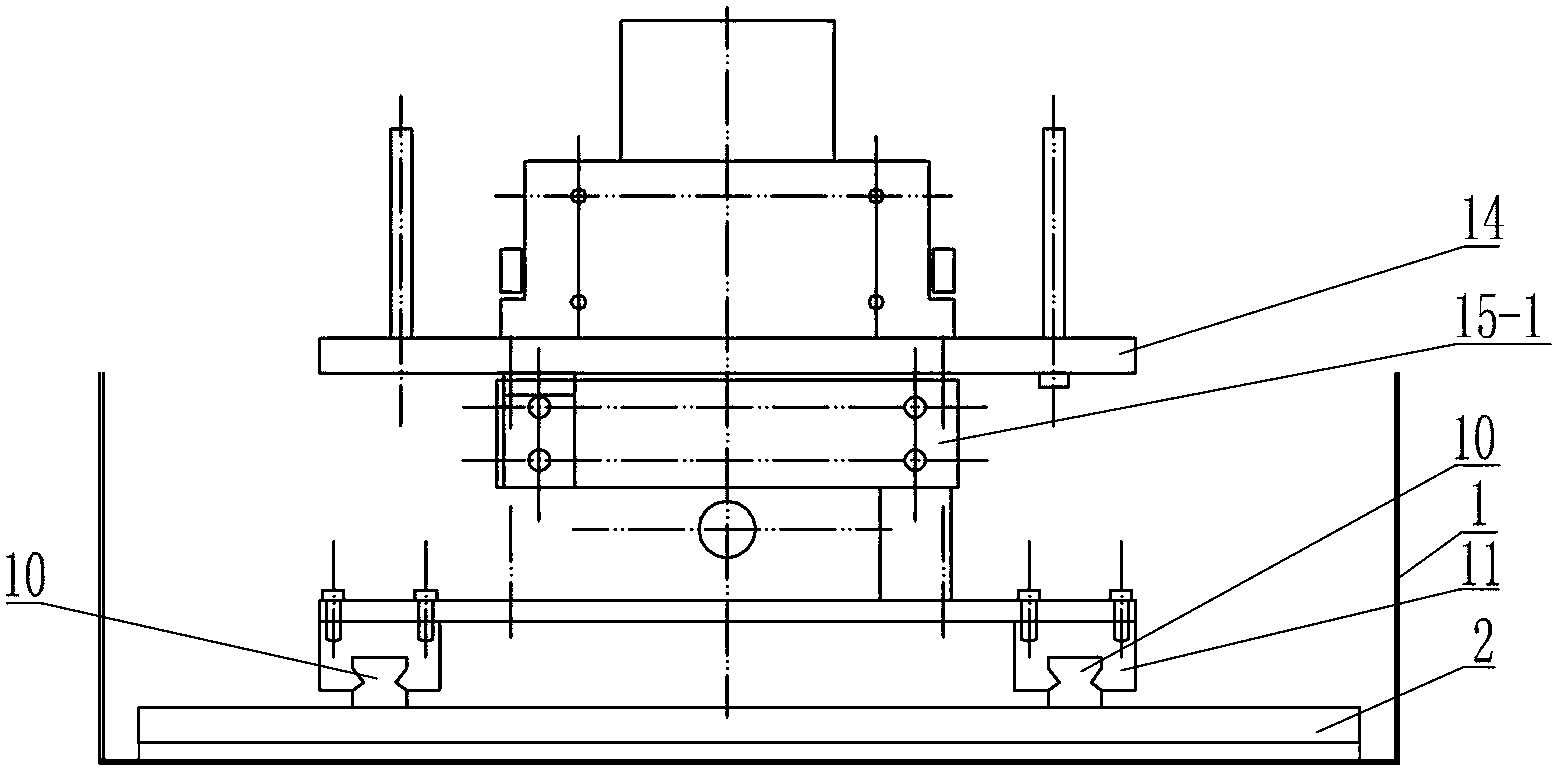
[0013] Specific implementation mode one: combine Figure 1 ~ Figure 4 To illustrate this embodiment, a loading device for testing the low-temperature performance of road joint filling materials in this embodiment includes an oil tank 1, a bearing plate 2, a transmission unit, a support sliding unit, and a loading unit;

[0014] The transmission unit includes a motor 3, a reducer 4, a first bevel gear 5, a second bevel gear 6, a transmission shaft 7, a fixed frame 8 and a transmission member 9;

[0015] The supporting slide unit includes a slide rail 10, a slide plate 11, a connection assembly 12 and a transition plate 13;

[0016] The loading unit includes a pressure sensor 16, a mobile loading platform 14, a fixed loading platform 19 and two sets of fixtures 15;

[0017] Fixture 8 is installed on the bearing plate 2 that is arranged on the bottom end surface of oil tank 1, and slide rail 10 is installed on the bearing plate 2, and slide plate 11 is installed on the slide rai...

specific Embodiment approach 2

[0021] Specific implementation mode two: combination figure 1 To illustrate this embodiment, the connection assembly 12 in this embodiment includes two connection plates 12-1, both of which are L-shaped, and the horizontal section of one connection plate 12-1 is detachably connected to the slide plate 11 , wherein the vertical section of one connecting plate 12-1 is detachably connected to the vertical section of the other connecting plate 12-1, and the horizontal section of the other connecting plate 12-1 is detachably connected to the corresponding platform 14. With such a setting, the connection and installation are convenient, and the design requirements and actual needs are met. Others are the same as in the first embodiment.

specific Embodiment approach 3

[0022] Specific implementation mode three: combination figure 1 Describe this embodiment, the device described in this embodiment also includes a stop post 17, the stop post 17 is vertically arranged, the stop post 17 is installed on the lower end surface of the platform 14 connected with the slide plate 11, and the transmission member 9 is located between the transition plate 13 and the stop. Between columns 17. Such arrangement facilitates the blocking of the transfer member from retreating. Others are the same as in the first embodiment.


PUM


Abstract

The invention discloses a loading device used in a road seam filling material low-temperature performance test, and relates to a material low-temperature performance test loading device. With an existing loading device, test sample assembly speed is low, and loading is carried out with a slide way manner such that certain resistance is caused and test precision is influenced. The invention aims at solving the problems. The device provided by the invention comprises an oil tank, a bearing plate, a transmission unit, a supporting sliding unit, and a loading unit. The transmission unit comprises a motor, a speed reducer, a first bevel gear, a second bevel gear, a transmission shaft, a fixed rack, and a transmission part. The supporting sliding unit comprises a slide rail, a slide plate, a connection assembly, and a transition plate. The loading unit comprises a pressure sensor, a mobile loading platform, a fixed loading platform, and two sets of fixtures. The fixed rack is arranged on the bearing plate arranged on the bottom end face of the oil tank. The slide plate is arranged on the slide rail and can slide on the slide rail. The output end of the motor and the input end of the speed reduced are connected. The first bevel gear is engaged with the second bevel gear. The device provided by the invention is used in the road seam filling material low-temperature performance test.

Description

technical field [0001] The invention relates to a loading device for a low-temperature performance test of materials, in particular to a loading device for testing the low-temperature performance of road joint filling materials, and belongs to the technical field of road surface maintenance. Background technique [0002] At present, there are various types of joint filling materials on the market, and the quality is uneven, which often cannot achieve the expected maintenance effect. Some joint filling materials fail in the first winter after use. Repeated joint filling work has brought huge maintenance workload and economic loss. Therefore, it is very important to develop a set of equipment for evaluating the low-temperature performance of the joint filling material and the adhesion performance of the joint filling material and the joint wall. Previously, through literature search, the Chinese patent No. 200910072201.1 proposed a low-temperature performance tester for road ...

Claims


Application Information

Patent Timeline
Patent Type & Authority Applications(China)
IPC IPC(8): G01N3/18G01N3/02
Inventor 曹丽萍侯相琛薛恒潇雷学通
Owner HARBIN INST OF TECH
Why Eureka
Try Eureka