Visual positioning device and method for welding

A technology of visual positioning and welding device, which is applied to the cleaning method using gas flow, welding equipment, welding accessories and other directions. Improve welding efficiency, increase service life and reduce heat loss

Active Publication Date: 2021-09-17
安徽工布智造工业科技有限公司
View PDF6 Cites 0 Cited by
  • Summary
  • Abstract
  • Description
  • Claims
  • Application Information

AI Technical Summary

Problems solved by technology

[0004] Therefore, the present invention is made in view of the above problems. The present invention provides a welding visual positioning device and method to solve the need that the heat and spatter generated in welding affect the measurement accuracy of the sensor and the service life of the shielding parts is not long. Frequent replacement, and the use of shielding gas for welding will consume a lot of energy and other issues

Method used


Image

  • Visual positioning device and method for welding
  • Visual positioning device and method for welding
  • Visual positioning device and method for welding

Examples


Embodiment Construction

[0030] Preferred embodiments of the present invention will be described in detail with reference to the accompanying drawings so that those embodiments can be easily realized by those having ordinary skill in the art to which the invention pertains. However, the present invention can also be realized in various forms, so the present invention is not limited to the embodiments described hereinafter. In addition, in order to describe the present invention more clearly, parts not connected with the present invention will be omitted from the drawings.

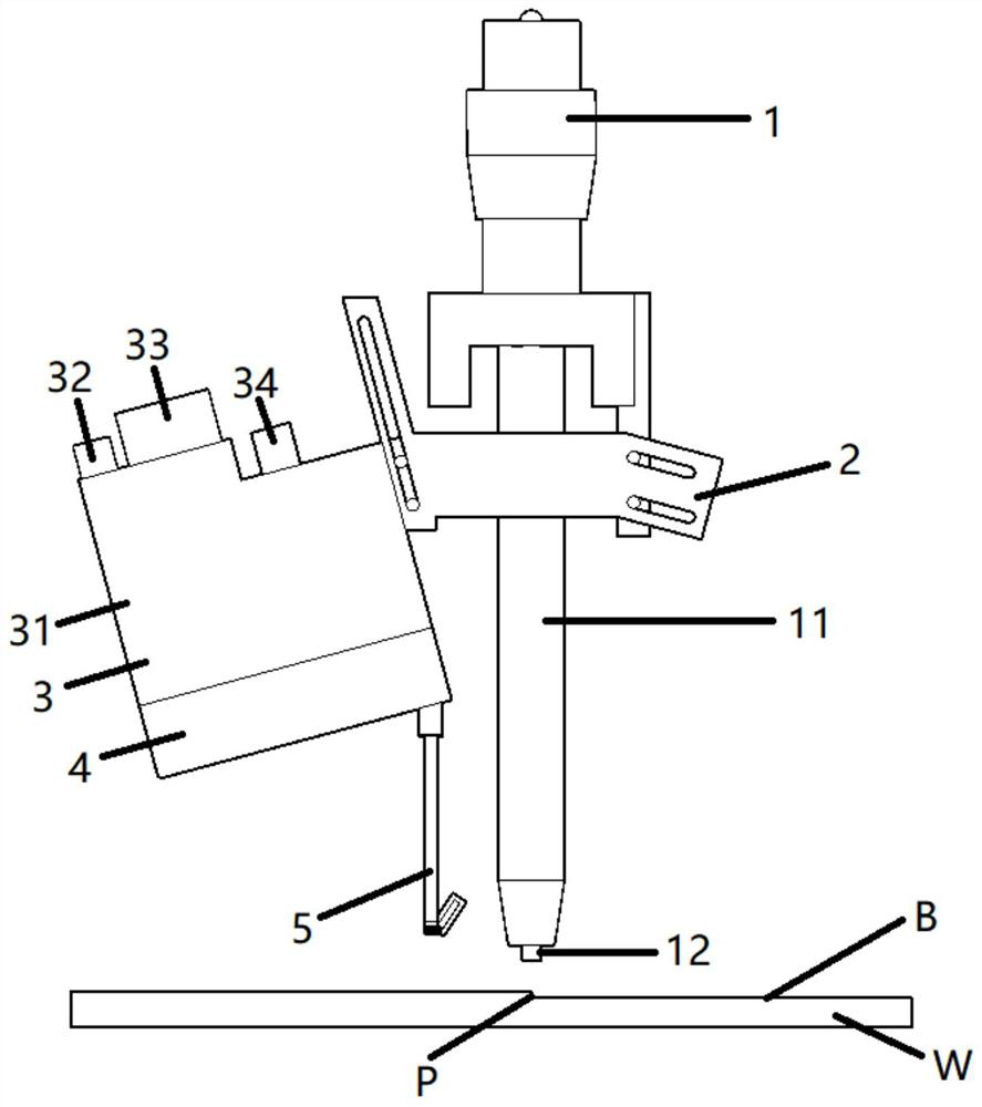
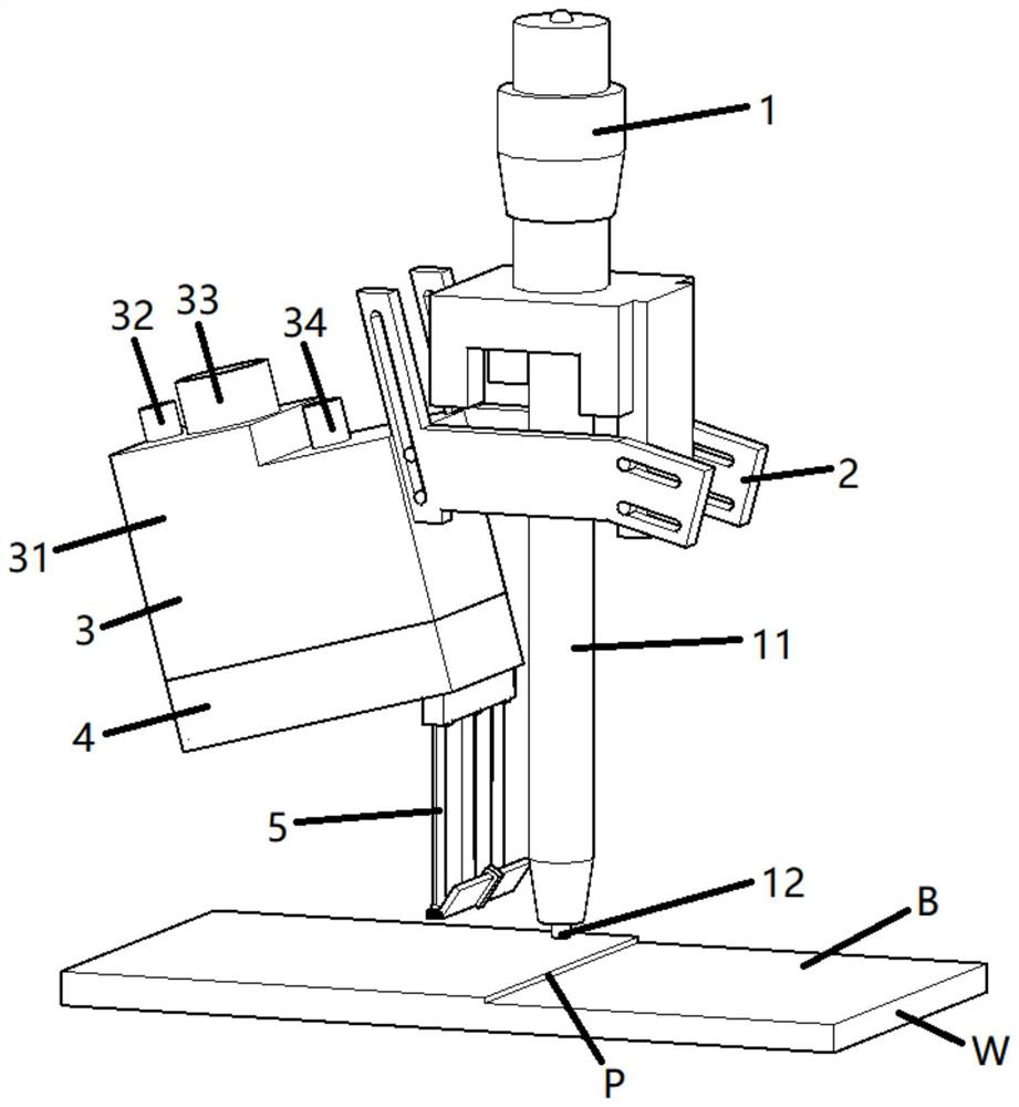
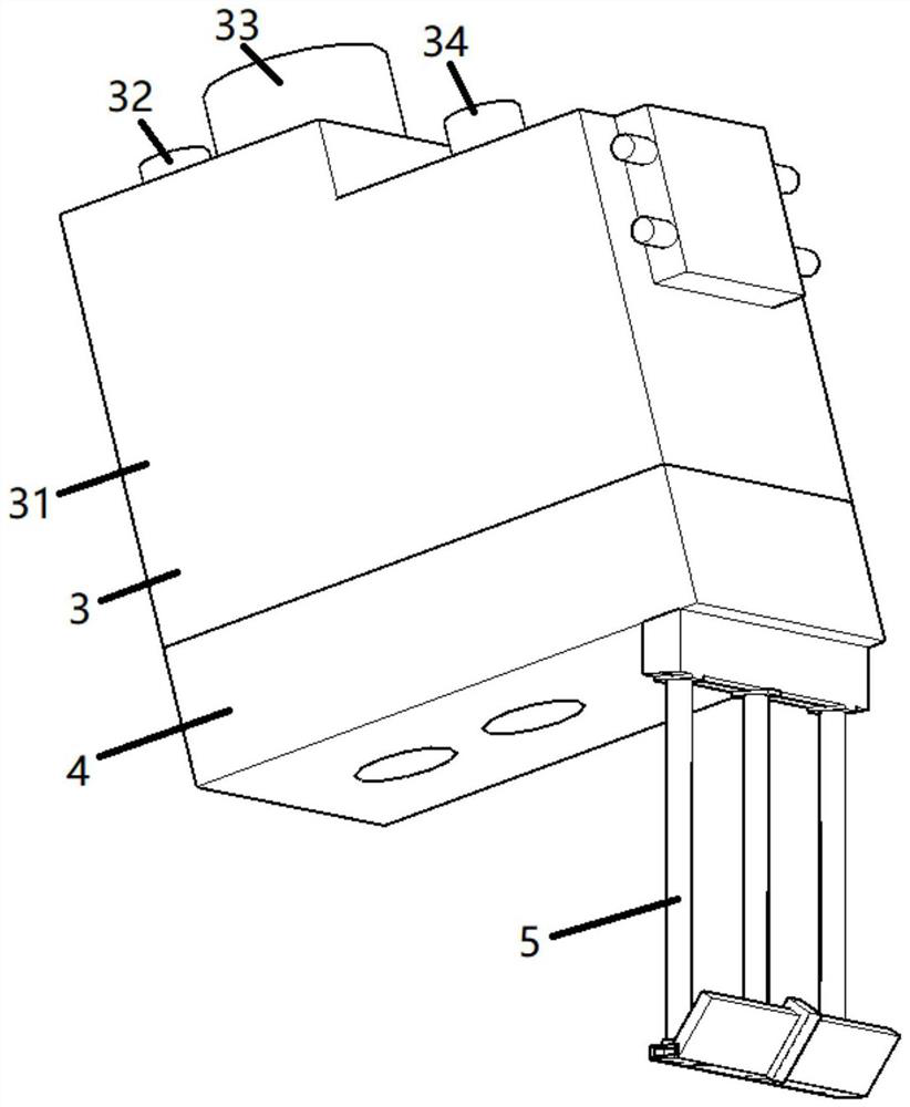
[0031] Such as figure 1 As shown, a visual positioning device for welding includes: a welding device 1, a fixture 2, a sensor unit 3, a protective cover 4, and a shielding part 5;

[0032] Such as figure 1 As shown, the sensor unit 3 according to this embodiment is mounted on the welding device 1 through the jig 2; the welding wire 12 is supplied to the welding torch 11 of the welding device 1; A voltage is applied between the w...


PUM


Abstract

The invention relates to the technical field of welding, in particular to a visual positioning device and method for welding. The visual positioning device comprises a welding device, a clamp, a sensor unit, a protective cover and a shielding part, the sensor unit is installed on one side of the welding device through the clamp, a welding torch is arranged at the lower end of the welding device, a welding wire is arranged at the lower end of the welding torch, a workpiece is arranged at the lower end of the welding wire, the sensor unit comprises a containing box, a gas supply port, a first connecting terminal, a second connecting terminal, a light transmitting plate, a light projection part, a detection part and a first gas flow path, and the gas supply port, the first connecting terminal and the second connecting terminal are arranged at the upper end of the containing box. A gas curtain frame is arranged in a rectangular parallelepiped pipeline of an air baffle plate in a sliding mode, the gas curtain frame is driven by fixed air pipes at two ends, the horizontal reciprocating motion of a sliding permanent magnet is achieved, the air baffle plate can be cleaned in time, and the service life of the air baffle plate is prolonged.

Description

technical field [0001] The invention relates to the field of welding, in particular to a visual positioning device and method for welding. Background technique [0002] Conventionally, when butt welding or the like is performed by arc welding or the like on workpieces such as a pair of iron plates having a groove shape, the welding torch is brought close to the workpiece (the butted groove-shaped portion). In this state, a voltage is applied between the tip of the welding wire supplied from the welding torch and the workpiece, and an arc is generated between them. In this way, the welding wire melts, the workpieces are heated and melted, and the workpieces can be welded together. [0003] When welding, the distance between the welding torch and the workpiece or the shape of the workpiece has an impact on the welding quality of the workpiece. Therefore, in the welding process of the prior art, a sensor needs to be used to measure the distance between the welding torch and th...

Claims


Application Information

Patent Timeline
IPC IPC(8): B23K9/16B23K9/32B08B5/02
CPCB23K9/16B23K9/32B08B5/02
Inventor 郭家友王继文侯克文王伟昌
Owner 安徽工布智造工业科技有限公司
Why Eureka
Try Eureka