Rigid push chain drive system

A technology of rigid push chain and drive system, which is applied in the field of mechanical transmission, can solve the problems of high manufacturing cost, interference, and various types of parts, and achieve the effects of ensuring safety and reliability, reducing the space occupied by the level, and improving the level of automation

Active Publication Date: 2022-03-11
CHINA NUCLEAR POWER TECH RES INST CO LTD +2
View PDF14 Cites 0 Cited by
  • Summary
  • Abstract
  • Description
  • Claims
  • Application Information

AI Technical Summary

Problems solved by technology

However, the transmission chain used in existing nuclear power plants can only drive the transport trolley in one horizontal direction, and it is prone to side bending when driving the transport trolley to move in the opposite direction, making it difficult to ensure the horizontal reciprocating movement of the transport trolley
[0003] Existing transmission chains used in other fields (non-nuclear power plants), such as Chinese patent CN202176674U, disclose a push chain, linear motion drive device and inspection bed, and have the following defects: (1) the internal and external push chain links are all shaped U-shaped structures , it is easy to cause interference during use, poor craftsmanship, high manufacturing cost, complicated assembly, and the connection strength cannot be guaranteed; (2) The layout is unreasonable, the entire stroke is easily limited by the size of the push chain box, and the stroke cannot be increased through modification; Disposal agencies that do not consider emergency situations cannot adapt to harsh working conditions
[0004] CN202926955U discloses a push chain, push chain transmission mechanism and hospital bed drive mechanism, which has the following defects: (1) the design structure of the inner and outer chain pieces is complicated, the parts are various, the processing technology is poor, and the cost is high; (2) the chain of complex structure The piece makes the chain link heavy, inconvenient to install and adjust, and the half-wrapped structure is inconvenient to maintain; (3) The push chain box installed horizontally occupies a large space and has a small volume, which limits the effective stroke of the push chain; there is no emergency disposal mechanism, Unable to adapt to harsh working conditions

Method used


Image

  • Rigid push chain drive system
  • Rigid push chain drive system
  • Rigid push chain drive system

Examples


Embodiment Construction

[0036] In order to have a clearer understanding of the technical features, purposes and effects of the present invention, the specific implementation manners of the present invention will now be described in detail with reference to the accompanying drawings.

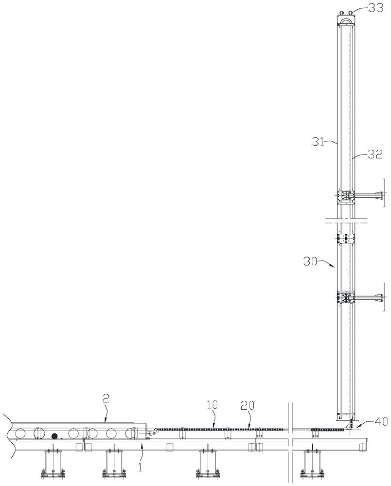
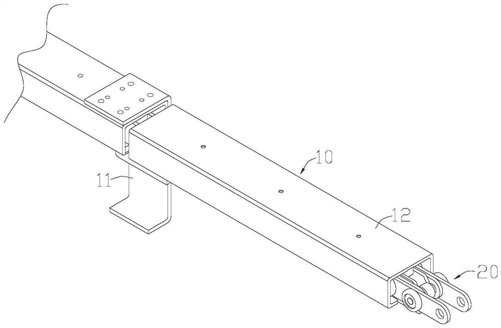
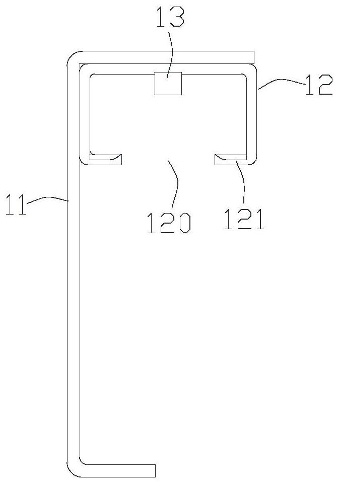
[0037] Such as figure 1 As shown, a rigid push chain drive system according to an embodiment of the present invention can be used for nuclear fuel transfer, and it can include a guide rail 10 , a rigid push chain 20 , a chain storage mechanism 30 and a sprocket mechanism 40 .

[0038] One end of the guide rail 10 is connected to the transport guide rail 1 , so that the transport trolley 2 can travel from the transport guide rail 1 to the guide rail 10 . The rigid push chain 20 is arranged in the guide rail 10 and fixedly connected with the transport trolley 2. The rigid push chain 20 can move back and forth along the axial direction of the guide rail 10, thereby pushing and pulling the transport trolley 2 to realize the...


PUM


Abstract

The rigid push chain driving system comprises a guide rail, a rigid push chain arranged on the guide rail, a chain storage mechanism vertically arranged at the end, away from a conveying guide rail, of the guide rail, and a chain wheel mechanism arranged between the chain storage mechanism and the guide rail. The rigid push chain comprises a chain push head, a head chain link, a plurality of first chain links, a plurality of second chain links and a plurality of U-shaped inner chain blocks. The multiple first chain links are arranged at intervals in the extending direction of the rigid push chain, each second chain link is arranged on the inner side of the corresponding first chain link and connected between every two adjacent first chain links in series, and a chain is formed by the second chain links and the first chain links; the head chain link is arranged between one end of the chain and the chain pushing head and is respectively hinged with the chain and the chain pushing head; the multiple inner chain blocks are sequentially connected in the extending direction of the rigid push chain and matched in the chain. The problem of bidirectional driving of nuclear fuel transfer in a narrow space is solved, horizontal reciprocating motion of the transport trolley is achieved, and the accuracy of linear motion of the transport trolley is improved.

Description

technical field [0001] The invention relates to the technical field of mechanical transmission, in particular to a rigid push chain drive system. Background technique [0002] In nuclear power plants, transport trolleys are mainly used for nuclear fuel transfer, and the horizontal reciprocating motion of the transport trolleys needs to be connected and driven by a transmission chain. However, the transmission chains used in existing nuclear power plants can only drive the transport trolley in one horizontal direction, and tend to bend sideways when driving the transport trolley in the reverse direction, making it difficult to ensure the horizontal reciprocating movement of the transport trolley. [0003] Existing transmission chains used in other fields (non-nuclear power plants), such as Chinese patent CN202176674U, disclose a push chain, linear motion drive device and inspection bed, and have the following defects: (1) the internal and external push chain links are all sha...

Claims


Application Information

Patent Timeline
Patent Type & Authority Applications(China)
IPC IPC(8): B66D3/00F16G13/06F16G15/12F16H19/06
CPCB66D3/006F16H19/06F16G13/06F16G15/12
Inventor 何之刘刚张志坚丁慧民郑传栋
Owner CHINA NUCLEAR POWER TECH RES INST CO LTD
Why Eureka
Try Eureka