
PLC-based (programmable logic controller-based) knife switch control method and system

A control method and control system technology, applied to electrical components, electric switches, circuits, etc., can solve problems such as difficulty in changing locking conditions, non-reusable auxiliary contacts, complicated circuit wiring, etc., to achieve easy changing of locking conditions, electrical operation circuit Reliable and Simplified Circuit Wiring Effects

Active Publication Date: 2013-08-07
GUANGDONG POWER GRID CO LTD DONGGUAN POWER SUPPLY BUREAU
View PDF3 Cites 8 Cited by
  • Summary
  • Abstract
  • Description
  • Claims
  • Application Information

AI Technical Summary

Problems solved by technology

[0012] 1) Auxiliary contacts cannot be reused, and there are too many cables: the electrical operation circuit of one knife switch uses the auxiliary contact of a certain switch. The switch introduces another pair of auxiliary contacts and lays another cable; in addition, in addition to the auxiliary contacts required for the electrical operation circuit of the knife switch, equipment such as the measurement and control panel also needs to receive the position information switch of the knife switch, so additional auxiliary contacts must be installed. Contacts and cables are used for the measurement and control panel and other equipment, making the loop wiring more complicated;
[0013] 2) It is difficult to change the locking condition: If you want to change the locking condition of a certain knife switch, you need to change the line wiring, dig out the cable from the cable groove, and reconnect it to the auxiliary contact of the relevant knife switch

Method used


Image

  • PLC-based (programmable logic controller-based) knife switch control method and system
  • PLC-based (programmable logic controller-based) knife switch control method and system
  • PLC-based (programmable logic controller-based) knife switch control method and system

Examples


Embodiment Construction

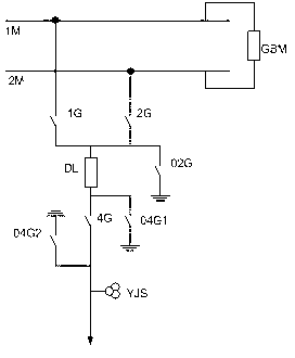
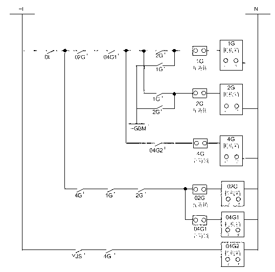
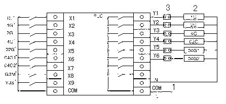
[0036] Attached below figure 1 , 3 A kind of PLC-based knife switch control method and system of the present invention are further described:

[0037] A PLC-based knife switch control system of the present invention includes a bus tie switch GBM on the bus 1M and 2M, a switch DL in a certain interval, isolating knife switches 1G, 2G, 4G, grounding knife switches 02G, 04G1, 04G2, lines Voltage relay YJS, and PLC, AC power supply 1, mechanism box 2 of each switch and several five-proof locks 3, switch DL, isolation switch 1G, 2G, 4G, grounding switch 02G, 04G1, 04G2, bus coupler One end of the auxiliary contacts DL', 1G', 2G', 4G', 02G', 04G1', 04G2', GBM', YJS' of the switch GBM and the line voltage relay YJS correspond to the X1~X9 input terminals of the PLC one by one Connected, the other end of them is connected in parallel to the COM input terminal of the PLC, and the position information switch value is sent to the PLC, so that the PLC can share information with other pe...


PUM


Abstract

A PLC-based (programmable logic controller-based) knife switch control method includes the steps of firstly, inputting location switching value of a bus tie switch on a bus and location switching values of switches, an isolator, an earthing knife switch and a circuit voltage relay which are at certain intervals to a PLC; secondly, connecting live and zero wires of a power supply and mechanism boxes of the knife switches to the PLC; thirdly, programming in the PLC to define operation conditions of the knife switches according to location features of the switches, the isolator, the earthing knife switch and the circuit voltage relay which are at certain intervals; fourthly, during operation of the knife switches, judging whether the operation conditions of the knife switches are met or not by the PLC so as to determine whether to connect the power supply to the mechanism box of the corresponding knife switch or not, and thereby controlling operability of the knife switch. The PLC-based knife switch control method and system enable an electrical operation circuit of the knife switches to be simple to connect and convenient to maintain and modify.

Description

technical field [0001] The invention relates to the technical field of knife switch control in electric power systems, in particular to a knife switch electrical control method and system using PLC to judge operating conditions. Background technique [0002] A knife switch is an isolating switch with a visible opening point. The breaker in the power system includes the isolation breaker and the grounding breaker. In the power system, the power-off equipment is separated from the live equipment by separating the isolation knife switch; and the power-off equipment is connected to the ground by closing the grounding knife switch, so that the staff can safely touch the power-off equipment. [0003] figure 1 It shows the schematic diagram of the switch connection in a bay, that is, the primary wiring diagram of a power supply line connected to the busbar. Generally, multiple lines can be connected to one bus, that is, there are multiple intervals. The blocking circuit of the ...

Claims


Application Information

Patent Timeline
IPC IPC(8): H01H9/20H01H9/54
Inventor 卢迪勇周锡球张言权侯汝锋姚文达曾睿梁海华刘洋刘钦豪
Owner GUANGDONG POWER GRID CO LTD DONGGUAN POWER SUPPLY BUREAU
Learn More