Equal-directional array type rectifier bridge stack

A rectifier bridge stack and array technology, which is applied in the direction of converting AC power input to DC power output, output power conversion devices, electrical components, etc., can solve the problems of large resource consumption, large plane area, loose structure, etc., and achieve The effect of reducing raw materials, reducing the plane area, and reducing costs

Active Publication Date: 2013-08-07
YANGZHOU YANGJIE ELECTRONIC TECH CO LTD
View PDF5 Cites 4 Cited by
  • Summary
  • Abstract
  • Description
  • Claims
  • Application Information

AI Technical Summary

Problems solved by technology

In order to overcome the problem of needing to distinguish the placement direction of the chip, the structure of the frame was adjusted, but the structural design of the case, firstly, it is necessary to identify whether the corner is a segmented surface or an acute corner plane, so as to complete the welding work of the PN junction ; Second, the overall structure of the frame makes the final product have a large planar area, large volume, loose structure, consumes more resources, and the cost of the product is still at a high level

Method used


Image

  • Equal-directional array type rectifier bridge stack
  • Equal-directional array type rectifier bridge stack

Examples


Embodiment Construction

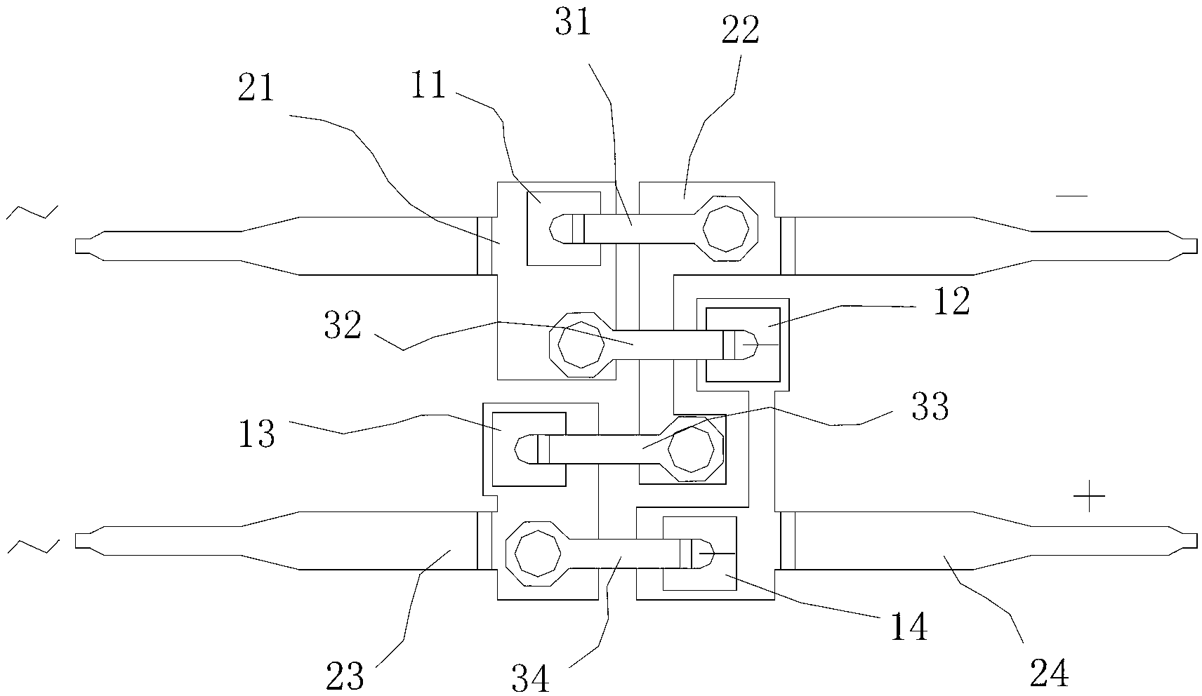
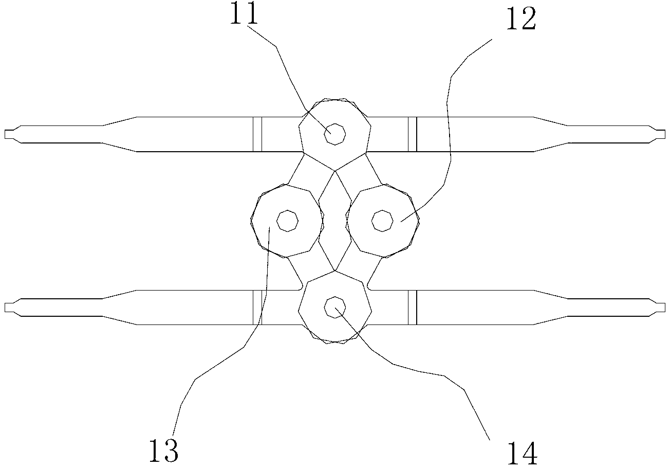
[0020] The present invention as figure 1 As shown, it includes chips 1~4 11~14, frames 1~4 21~24 and jumpers 1~4 31~34. The frames 1~4 11~14 are composed of their respective bodies and pins. The above-mentioned frame is arranged on the opposite side, wherein the bodies of the frame one 21 and the frame three 23 are rectangular, keep an insulating distance between them, and are on one side of the opposite side layout; the two frames 22 and the four frames 24 The body is C-shaped, and they are in a occlusal position relationship with each other, and keep an insulating distance, and are located on the other side of the opposite side layout; the chip one 11 is arranged on the front of the frame one 21 body, and the chip two 12 and chip four 14 are respectively arranged on the front of the frame four 24 body, the chip three 13 is arranged on the front of the frame three 23 body, and the polarities of the chips one to four 11 to 14 are in the same direction;

[0021] The jumper on...


PUM


Abstract

The invention provides an equal-directional array type rectifier bridge stack which is compact in structure and more reasonable in whole layout, so that the volume and the cost of a product are effectively reduced. The equal-directional array type rectifier bridge stack comprises a chip I, a chip II, a chip III and a chip IV, a framework I, a framework II, a framework III and a framework IV, a jumper wire I, a jumper wire II, a jumper wire III and a jumper wire IV; each one of the framework I, the framework II, the framework III and the framework IV is formed by a respective body and a pin; the four frameworks are in an opposite-side layout; the bodies of the framework I and the framework III are rectangular; an insulating distance is kept between the bodies and the bodies are located at one side of the opposite-side layout; the bodies of the framework II and the framework IV are C-shaped, and the bodies are in an occlusion position relation; an insulating distance is kept between the bodies and the bodies are located at the other side of the opposite-side layout; the chip I is distributed on the front face of the body of the framework I; the chip II and the chip IV are respectively distributed on the front face of the body of the framework IV; the chip III is distributed on the front face of the body of the framework III; and the directions of polarities of the chip I, the chip II, the chip III and the chip IV are the same. According to the equal-directional array type rectifier bridge stack disclosed by the invention, the quality of a product is stable and the cost is greatly reduced.

Description

technical field [0001] The invention relates to the improvement of the single-phase diode rectification bridge stack chip structure. Background technique [0002] Single-phase diode rectifier bridge stack in the prior art such as figure 2 As shown, it has two lead frames. Due to the structural relationship, the P side (small) of chip one 11 and chip four 14 faces downward, and the N side (large side) of chip two 12 and chip three 13 face down. This structure has been used in this field until now. In production, the operator needs to carefully distinguish and place the chips. If there is a mistake in the placement, the finished product will be scrapped, requiring the operator to concentrate on it, which makes the labor intensity of the operator relatively high. Large, low production efficiency. Although the area of ​​the large surface and the small surface is not much different, when in use, the large surface is close to the heat dissipation surface to improve the heat diss...

Claims


Application Information

Patent Timeline
Patent Type & Authority Applications(China)
IPC IPC(8): H01L25/07H01L23/495H02M7/00
CPCH01L2924/0002H01L2224/40245H01L2924/00
Inventor 王双王毅
Owner YANGZHOU YANGJIE ELECTRONIC TECH CO LTD
Why Eureka
Try Eureka