
Dynamic aperture control and normalization for apodization in beamforming

A dynamic aperture and normalization technology, applied in ultrasonic/sonic/infrasonic equipment control, acoustic re-radiation, material analysis using acoustic/ultrasonic/infrasonic, etc., can solve synchronization difficulties, synchronization, and dynamic aperture control types Difficulty and other issues

Active Publication Date: 2013-08-07
TEXAS INSTR INC
View PDF7 Cites 9 Cited by
  • Summary
  • Abstract
  • Description
  • Claims
  • Application Information

AI Technical Summary

Problems solved by technology

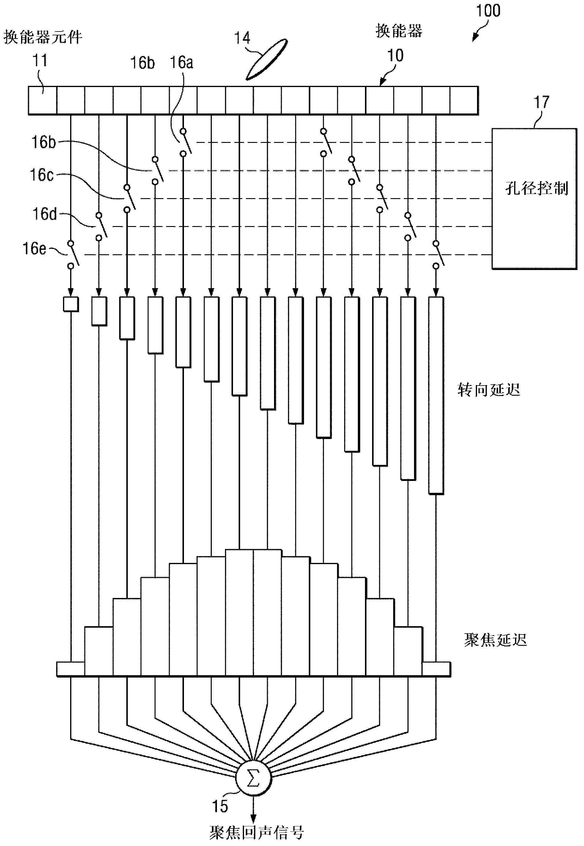
[0010] The type of dynamic aperture control implemented by conventional ultrasound beamformer systems 100 can be difficult to synchronize in terms of the number of active channels and sampling time, especially if the implementation is analog
Because of this synchronization difficulty, it often becomes more problematic to determine the data normalization required to keep the average signal level the same (constant) along the entire scan line as a function of sampling time

Method used


Image

  • Dynamic aperture control and normalization for apodization in beamforming
  • Dynamic aperture control and normalization for apodization in beamforming
  • Dynamic aperture control and normalization for apodization in beamforming

Examples


Embodiment Construction

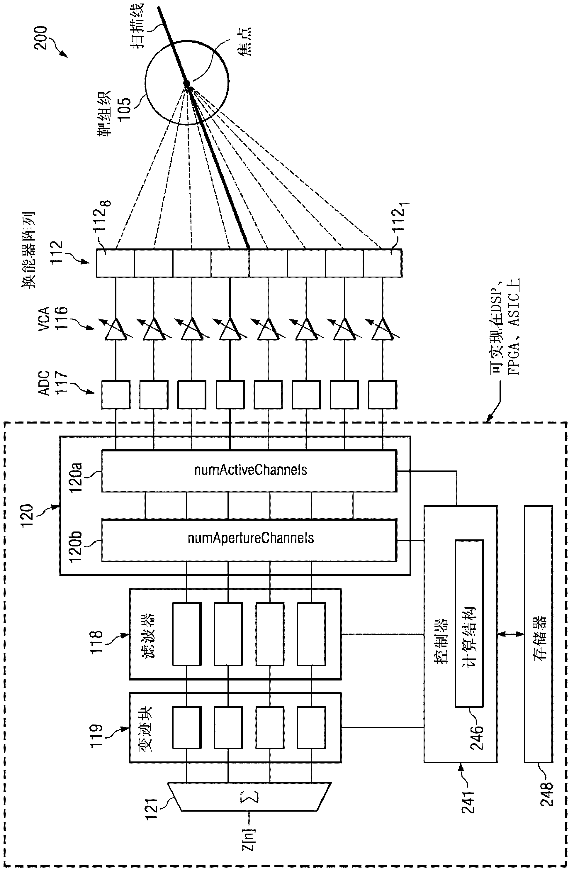
[0022] As noted above, a conventional ultrasound system such as the conventional ultrasound beamformer system 100 shown in FIG. Normalization (if implemented), the normalization of the summed channel data is used to scale the average signal level to be the same across the scanline in separate locations within the beamformer system (e.g., as independent data processing blocks) ( constant). Some parts of the signal processing may be performed in analog (eg aperture control 17) and some parts may be performed digitally (apodization, if implemented). In contrast, the disclosed integrated apodization method provides a software-based approach that performs dynamic aperture control and normalization, thereby combining the aforementioned separate data processing operations into a single operation to ensure data scaling accuracy and also eliminate the need for a switch.

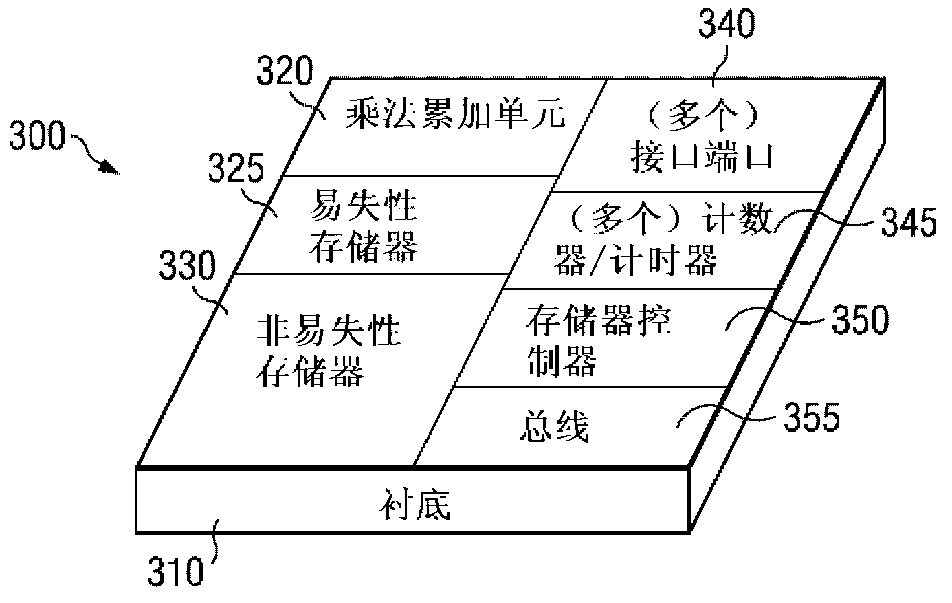
[0023] The disclosed software-based integrated apodization algorithm can be implemented on ICs such as ASICs, Fie...


PUM


Abstract

A method of apodizing for ultrasound beamforming includes providing filtered digital channel data representing echo data from target tissue in a plurality (k) of data channels and a predefined number of active channels (Nact). A software-based integrated apodization algorithm dynamically apodizes the digital channel data using a selected apodizing function h[n,k], n being the sample number. The integrated apodization algorithm applies dynamic aperture control to create an effective aperture by generating a parameter numApertureChannels (Nap[n]), where Nap[n]@Nact, and selecting Nap[n] particular data channels based on a dynamic beam focusing location for beamforming. Applied dynamic data scaling provides data normalization using a vector inner product between h[n,k] and a scale factor to generate normalized apodization factors hnorm [n,k]. The normalized apodization factors are applied to the digital channel data in the Nap[n] particular data channels to generate apodized and normalized digital channel data.

Description

technical field [0001] The disclosed embodiments relate to beamformers for ultrasound and related beamforming algorithms, integrated circuits (ICs) implementing the disclosed beamforming algorithms, and ultrasound systems therefor. Background technique [0002] Beamforming is a signal processing technique used in sensor arrays for directional signal transmission or reception. Spatial selectivity is obtained by using adaptive or fixed receive / transmit beam patterns. [0003] One medical application that uses beamforming is diagnostic ultrasound. Ultrasound energy is focused at the target tissue by a transmit beamformer, and ultrasound energy modulated and returned by the target tissue is focused by a receive beamformer. The receive beamformer may provide signals to generate ultrasound images, color Doppler or spectral Doppler information representing target tissue, or a combination thereof. Such beamforming systems can provide real-time cross-sectional (tomography) two-dim...

Claims


Application Information

Patent Timeline
IPC IPC(8): A61B8/00G06F19/00G01N29/24
CPCA61B8/54A61B8/4488G01S15/00A61B8/486G01S7/52047A61B8/5207
Inventor D·P·马吉
Owner TEXAS INSTR INC
Learn More