Cutting tool and method for manufacturing cut product using same

A cutting tool and cutting edge technology, applied in tool holders, cutting blades, manufacturing tools, etc., can solve the problems of poor reproducibility of cutting inserts, easy rotation of cutting inserts, and difficulty in fitting tolerances of cutting tools, etc. Achieves the effect of suppressing mounting stability and improving reproducibility

Active Publication Date: 2013-08-07
KYOCERA CORP
View PDF5 Cites 2 Cited by
  • Summary
  • Abstract
  • Description
  • Claims
  • Application Information

AI Technical Summary

Problems solved by technology

[0003] However, such cutting tools are difficult to engage due to dimensional tolerances as the number of concavities and convexities increases. For example, the reproducibility of mounting of the cutting insert may deteriorate, such as the cutting insert is fixed in a state tilted from the desired state. Case
Especially in the case of face grooving in which an annular groove is formed on the end surface of the workpiece, the cutting speed of the left and right cutting edges is different due to the difference in the machining diameter, so a torsional moment acts on the cutting edge to make the cutting Inserts rotate easily

Method used


Image

  • Cutting tool and method for manufacturing cut product using same
  • Cutting tool and method for manufacturing cut product using same
  • Cutting tool and method for manufacturing cut product using same

Examples


no. 1 approach

[0024] Below, use Figure 1 to Figure 6 A first embodiment of the cutting tool according to the present invention will be described.

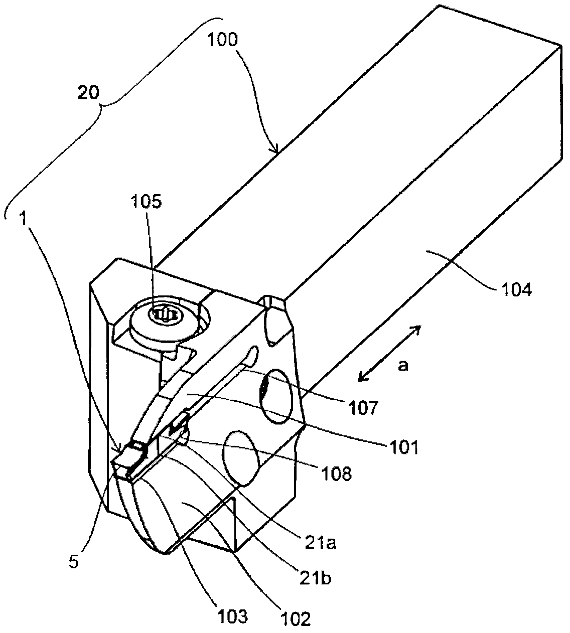
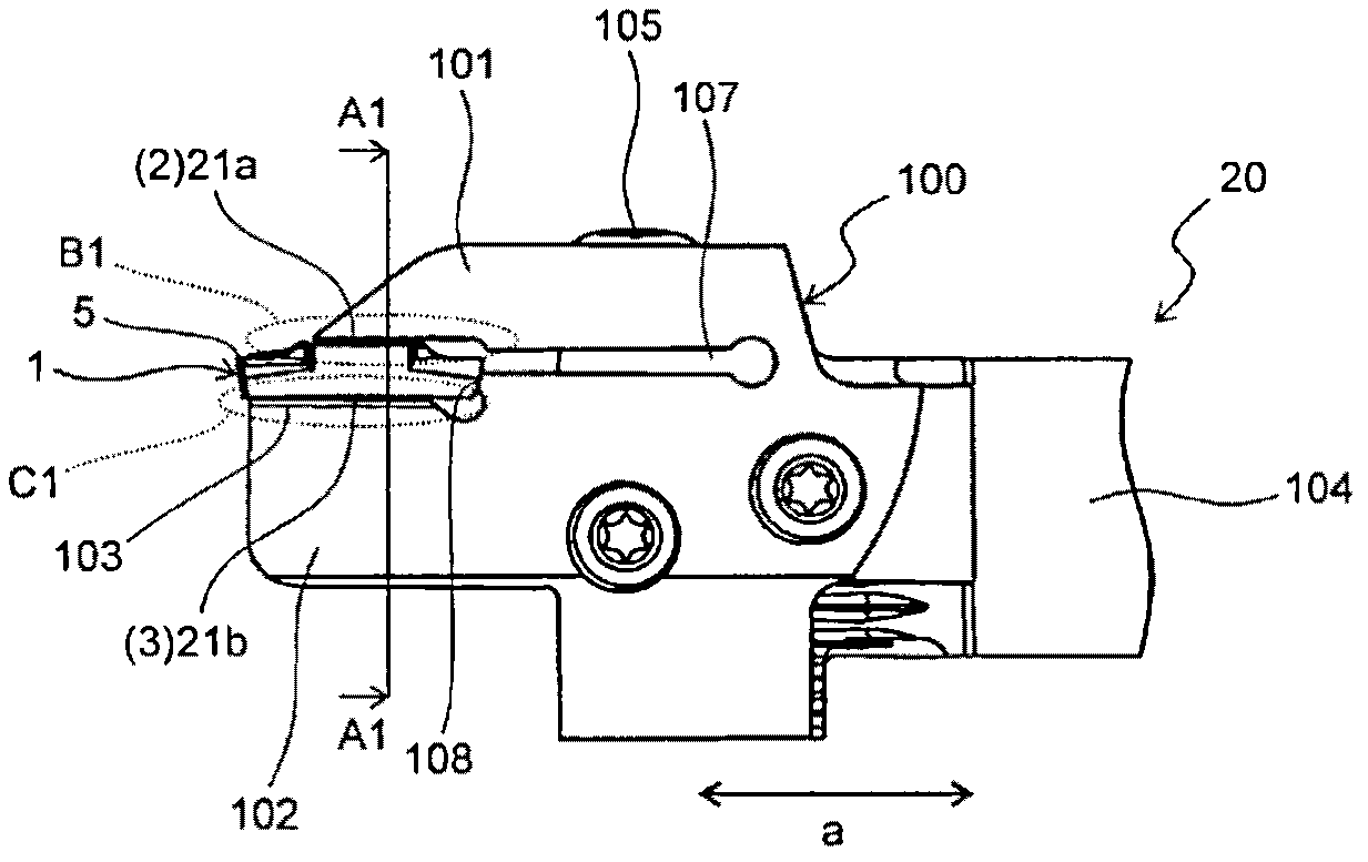
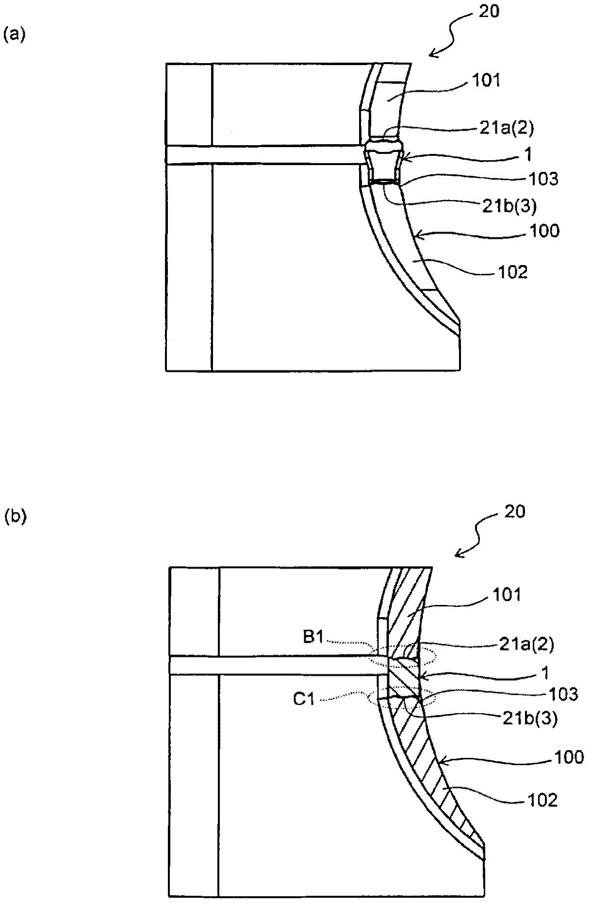
[0025] Such as figure 1 and figure 2 As shown, the cutting tool 20 of the present embodiment has a substantially prismatic shape, and includes a cutting insert (hereinafter, sometimes referred to as an “insert”) 1 and a holder 100 for fixing the insert 1 at the front end.

[0026] as described later Figure 6 As shown, the insert 1 has an upper surface 2 , a lower surface 3 and a cutting edge 5 on at least a portion of the upper surface 2 . Additionally, if figure 1 and figure 2 As shown, the holder 100 has an upper flange portion 101 and a lower flange portion 102 for fixing the insert 1 from the upper surface 2 and the lower surface 3 at the front end portion in the longitudinal direction indicated by the arrow a. Furthermore, the insert 1 is fixed to the holder 100 such that the cutting edge 5 protrudes from the front end of the hold...

no. 2 approach

[0066] Next, use Figure 7 ~ Figure 12 , the insert according to the second embodiment of the present invention will be described in detail. It should be noted that, in Figure 7 ~ Figure 12 , for the above Figure 1 to Figure 6The same components are assigned the same symbols, and explanations thereof are omitted.

[0067] Such as Figure 7 ~ Figure 9 and Figure 12 As shown, the cutting tool 20' of this embodiment has: an upper contact portion 21'a composed of the upper surface 2' of the insert 1' and the opposing surface of the upper flange portion 101' of the toolholder 100'; The lower contact portion 21'b is constituted by the opposing surface of the lower surface 3' of the insert 1' and the lower flange portion 102' of the holder 100'.

[0068] Such as Figure 10 As shown in (a), the upper contact portion 21'a has a second concave-convex surface 23' on the upper flange portion 101' of the holder 100', and has a first concave-convex surface 22' on the upper surface ...


PUM


Abstract

A cutting tool according to an embodiment of the present invention is configured in such a manner that either the upper contact section defined by the upper surface of a cutting insert and the upper jaw section of a holder and/or the lower contact section defined by the lower surface of the cutting insert and the lower jaw section of the holder has a first uneven surface section and a second uneven surface section. In a cross-section of the holder taken perpendicularly to the longitudinal direction of the holder, the distance (d1) between the tops of adjacent first protrusions among the first protrusions of the first uneven surface is less than the distance (d2) between the bottoms of adjacent second recesses among the second recesses of the second uneven surface, the adjacent second recesses being located so as to correspond to the adjacent first protrusions. A method for manufacturing a cut product using the cutting tool is also provided.

Description

technical field [0001] The present invention relates to a cutting tool and a method of manufacturing a machined object using the cutting tool. Background technique [0002] With respect to cutting tools, particularly throw away cutting tools for parting or grooving, studies have been made to suppress lateral misalignment of mounted cutting inserts. Japanese Patent Application Laid-Open No. 2004-223652 discloses a cutting tool in which a cutting insert and a holder are engaged by a plurality of concavities and convexities. This shape suppresses the positional displacement of the cutting insert due to the stress from the left-right direction of the cutting insert. [0003] However, such cutting tools are difficult to engage due to dimensional tolerances as the number of concavities and convexities increases. For example, the reproducibility of mounting of the cutting insert may deteriorate, such as the cutting insert is fixed in a state tilted from the desired state. Case. ...

Claims


Application Information

Patent Timeline
Patent Type & Authority Applications(China)
IPC IPC(8): B23B27/16B23B27/04
CPCB23B29/043B23B27/1611B23B27/04B23B2220/126B23B27/045B23B2205/02Y10T82/10Y10T407/2282B23B27/16B23B2200/167B23B2205/12B23B2260/132
Inventor 井上善弘
Owner KYOCERA CORP
Why Eureka
Try Eureka