
nursing bed

A nursing bed and backboard technology, which is applied in the field of nursing beds, can solve the problems of bulky structure and single function, and achieve the effects of stable transmission, low precision requirements, and low noise

Active Publication Date: 2016-04-13
郎冲
View PDF5 Cites 0 Cited by
  • Summary
  • Abstract
  • Description
  • Claims
  • Application Information

AI Technical Summary

Problems solved by technology

There are still many such examples, and they have a disadvantage that they are limited by the bed support, have a bulky structure, and have a single function.

Method used


Image

  • nursing bed
  • nursing bed
  • nursing bed

Examples


Embodiment Construction

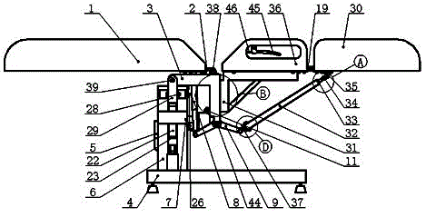
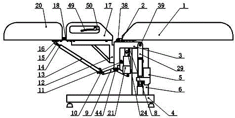
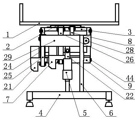
[0029] like figure 1 and 3 Shown, a kind of nursing bed, it comprises base 4, is provided with column 6 and crossbeam drive mechanism on base 4, is provided with long shaft 28 horizontally on column 6 top, and one end of crossbeam 29 is hinged on column 6 by long shaft 28 , the middle part of the crossbeam 29 pivots at a certain angle around the long rotating shaft 28 under the drive of the crossbeam driving mechanism. The beam driving mechanism includes a first motor 5 fixed on the base 4, the middle part of the beam 29 is hinged with the head of the first transmission sleeve 22, and the first transmission sleeve 22 is sleeved on the first transmission wire driven by the first motor 5. A screw drive is formed on the bar 23 , and the beam 29 pivots at a certain angle around the long rotating shaft 28 under the drive of the first motor 5 .

[0030] The two ends of the crossbeam 29 naturally extend upwards to the shaft holder, and the shaft holder is horizontally provided wit...


PUM


Abstract

A nursing bed comprises a base and stand columns arranged on the base. A center support frame is arranged on the stand columns and comprises a transverse beam and a front-and-back tilting support; one end of a back plate supporting seat is hinged at the front end of the front-and-back tilting support through a back plate rotating shaft; the middle portion of the back plate supporting seat is connected with a back plate driving mechanism; two pairs of hinge shafts are arranged in the vertical direction of the back of the front-and-back tilting support to achieve the connection of a left straddle support and a right straddle support, the left straddle support is fixedly provided with a left middle plate and a left leg plate, and the right straddle support is fixed provided with a right middle plate and a right leg plate.

Description

technical field [0001] The proposal relates to a bed, in particular to a nursing bed. Background technique [0002] There are many kinds of nursing beds in the prior art. For example, Chinese utility model patent 200720169410.4 relates to an automatic nursing bed, which includes a bed bracket and its lower bed frame. The bed bracket consists of a back bracket, a hip bracket, a thigh bracket and The four parts of the foot bracket are hinged. The hinges on the left and right sides of the bracket are the first connection point, the second connection point, and the third connection point. The rotatable beam on the bed frame is connected to an electric screw rod. It is connected with the back bracket, the first connecting rod is hinged between the left and right side panels of the buttock bracket between the first connection point and the second connecting rod is hinged between the second connecting point and the third connecting point, and the first connecting rod is connected t...

Claims


Application Information

Patent Timeline
Patent Type & Authority Patents(China)
IPC IPC(8): A61G7/005A61G7/008A61G7/02
Inventor 郎冲
Owner 郎冲
Learn More