Embedded steel column leg with steel pin

An embedded steel column foot and steel dowel technology, applied in the direction of construction and building structure, can solve the problems of unfavorable construction, complicated column foot method, large pull-up force, etc.

Inactive Publication Date: 2010-06-30
BEIJING UNIV OF TECH
View PDF0 Cites 8 Cited by
  • Summary
  • Abstract
  • Description
  • Claims
  • Application Information

AI Technical Summary

Problems solved by technology

However, as buildings develop toward higher heights and larger spans, the columns will generate huge uplift forces under the action of horizontal earthquakes and winds. complex, unfavorable construction

Method used


Image

  • Embedded steel column leg with steel pin
  • Embedded steel column leg with steel pin
  • Embedded steel column leg with steel pin

Examples


Embodiment 1

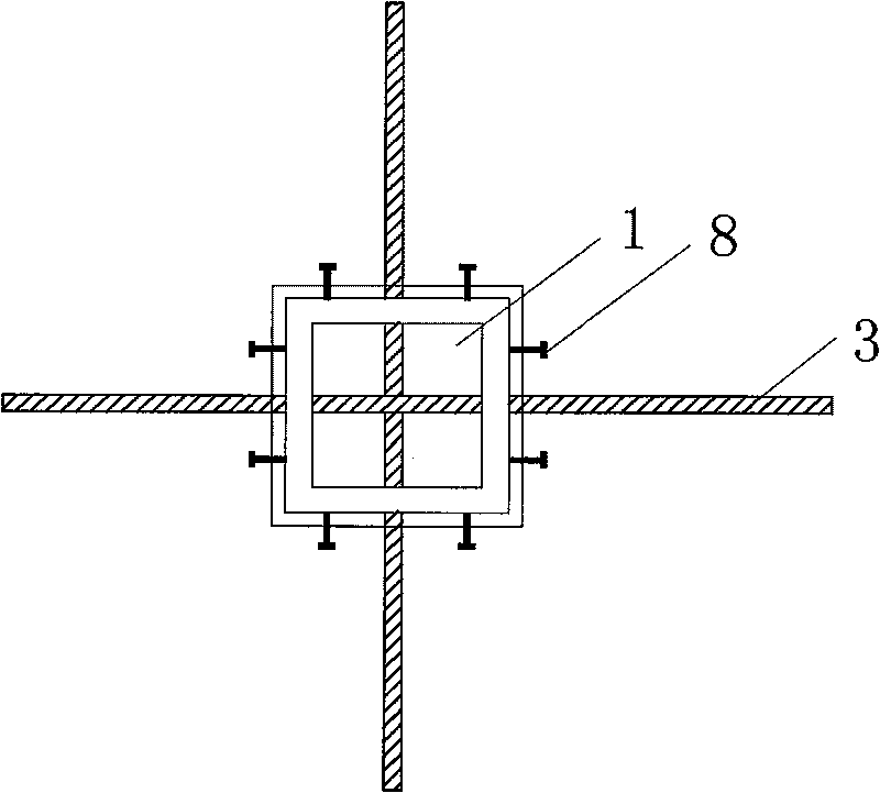
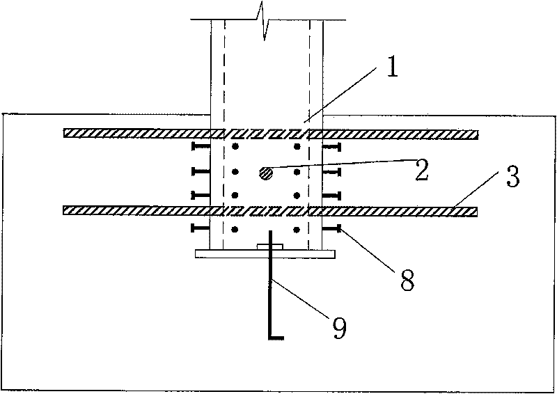
[0024] Such as figure 1 , figure 2 As shown, in this embodiment, horizontal through holes 2 are opened in the embedded part of the steel column foot 1, and the horizontal through holes 2 are evenly distributed along the height direction. Then penetrate steel pins in the hole 2 (it can be steel bars 3, variable-section steel rods 4 or various types of steel 5, the diameter can be selected according to the force requirements and should not be less than 18mm, and the vertical center distance of the steel pins should not be less than 500mm , the anchorage length of both ends of the steel pin in the foundation should not be less than 30d (d is the diameter of the steel pin), and the two adjacent steel pins along the height direction should be placed alternately and should be connected with the steel bars in the foundation. The part of the steel plate embedded in the foot of the steel column should be Thicken or add stiffeners or stiffeners at the openings to prevent extrusion or ...

Embodiment 2

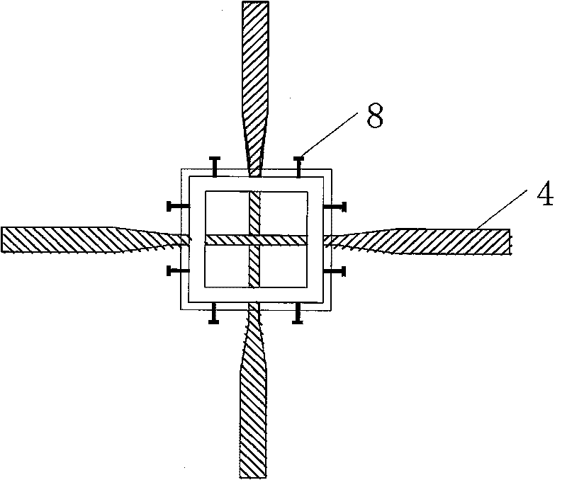
[0029] Such as image 3 As shown, the structure of this embodiment is basically the same as that of Embodiment 1, the only difference is that the steel rod has a variable cross-section. This kind of steel bar needs to be divided into two sections to make. During construction, the longer section is first passed through the steel column, and then the shorter section of steel bar is welded to the longer steel bar at the joint. This kind of variable cross-section steel rod can reduce the weakening of the steel column by the opening, and at the same time, the contact surface between the steel rod and the concrete becomes larger, which can provide greater pull-out resistance. However, it is necessary to check the bearing capacity at the variable section of the steel bar and at the weld.

Embodiment 3

[0031] Such as Figure 4 As shown, the structure of this embodiment is basically the same as that of Embodiment 1, the only difference is that the steel pins implementing the present invention are I-beams, and the openings of the steel columns should be changed accordingly during construction.


PUM


Abstract

The invention discloses an embedded steel column leg with a steel pin, which belongs to one of steel-structure column leg construction practices in building structure. The flange of the embedded part of the steel column leg is provided with a hole; the steel pin pentrates the steel column leg, the two steel pins which are adjacent along the height direction are staggeredly placed and are connected with steel bars in a base. The steel plate of the embedded part of the steel column leg is thickened or the location with the hole is provided with stiffening ribs or stiffening plates, in order to prevent the extrusion or the tearing damage between the steel rod and the steel plate. Through the effect of the steel pin, the invention not only can ensure the reliability of the connection of the column leg and the base, but also can ensure the overall force of the column leg and the base when the column leg bears load, thereby increasing the carrying capacity and improving the deformation capacity.

Description

technical field [0001] The invention relates to an embedded steel column base with steel pins, which belongs to a construction method of steel structure column bases of building structures. Background technique [0002] In steel structure buildings, the function of the column foot is to reliably transmit the internal force of the column to the foundation and firmly connect with the foundation, so the construction method of the column foot is very important for the safety of the structure, and at the same time, the column foot is relatively expensive in the entire column. Steel is also a labor-intensive part, so the selection and design of column feet is one of the key technologies in the overall design. [0003] The specific structure of the column foot depends on the cross-sectional form of the column and the connection method between the column and the foundation. There are two forms of connection between the column and the foundation: rigid connection and hinge connectio...

Claims


Application Information

Patent Timeline
Patent Type & Authority Applications(China)
IPC IPC(8): E04B1/41E04B1/58
Inventor 曹万林王金王立长张建伟
Owner BEIJING UNIV OF TECH
Why Eureka
Try Eureka