Electrical hydraulic combined discharging device

An unloading device, electro-hydraulic technology, applied in the direction of transportation and packaging, loading/unloading, conveyor objects, etc., can solve the problem of the gravity impact of coal blocks on the belt, the accumulation of splashing and scattering, the inability to solve the problem of belt gravity impact, splashing and scattering Accumulation and conveying machinery require high synchronization to achieve the effect of ensuring force balance and operating safety, improving operating efficiency, and good overall mechanical properties

Inactive Publication Date: 2011-04-06
JIANGSU KACHUANG MACHINERY
View PDF1 Cites 8 Cited by
  • Summary
  • Abstract
  • Description
  • Claims
  • Application Information

AI Technical Summary

Problems solved by technology

In the process of coal selection and coal yard storage and transportation, most of the joint operations of multiple belt conveying machines are used. When the coal is transferred to the transition, due to the gravity impact of the coal on the belt, the splashing and accumulation of the coal cannot be solved, resulting in the operation The environment is harsh, the conveying machinery is damaged, the normal operation rate is low, the maintenance workload is heavy and the cost is high
At present, during the joint operation of domestic coal selection and dumping with multiple conveying machinery, the transition method when the coal is changed to conveying is completed by using a conical hopper or a material distribution device. The disadvantage of this method is that the synchronization of the conveying machinery is high. ; It cannot solve the gravity impact of coal on the belt, splashing and accumulation; when the operation cycle is intermittent and frequent, the problems of high failure rate of conveying machinery, low normal operation rate, large maintenance workload and high cost are particularly obvious
Chinese patent 200820079966.9 discloses a swing-type dust-free unloading device, which uses a vertical spiral blanking barrel to reduce the large drop of powdery materials in the space, thereby reducing dust, but the effect is poor

Method used


Image

  • Electrical hydraulic combined discharging device
  • Electrical hydraulic combined discharging device
  • Electrical hydraulic combined discharging device

Examples


Embodiment Construction

[0017] The present invention will be further described below in conjunction with accompanying drawing, so that structure and function of the present invention are better understood:

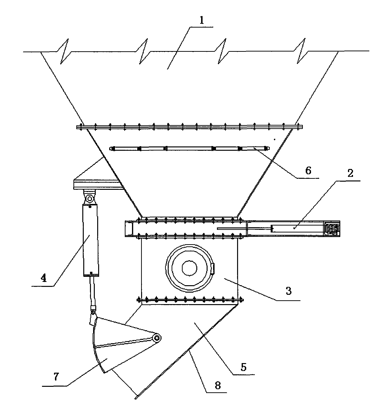
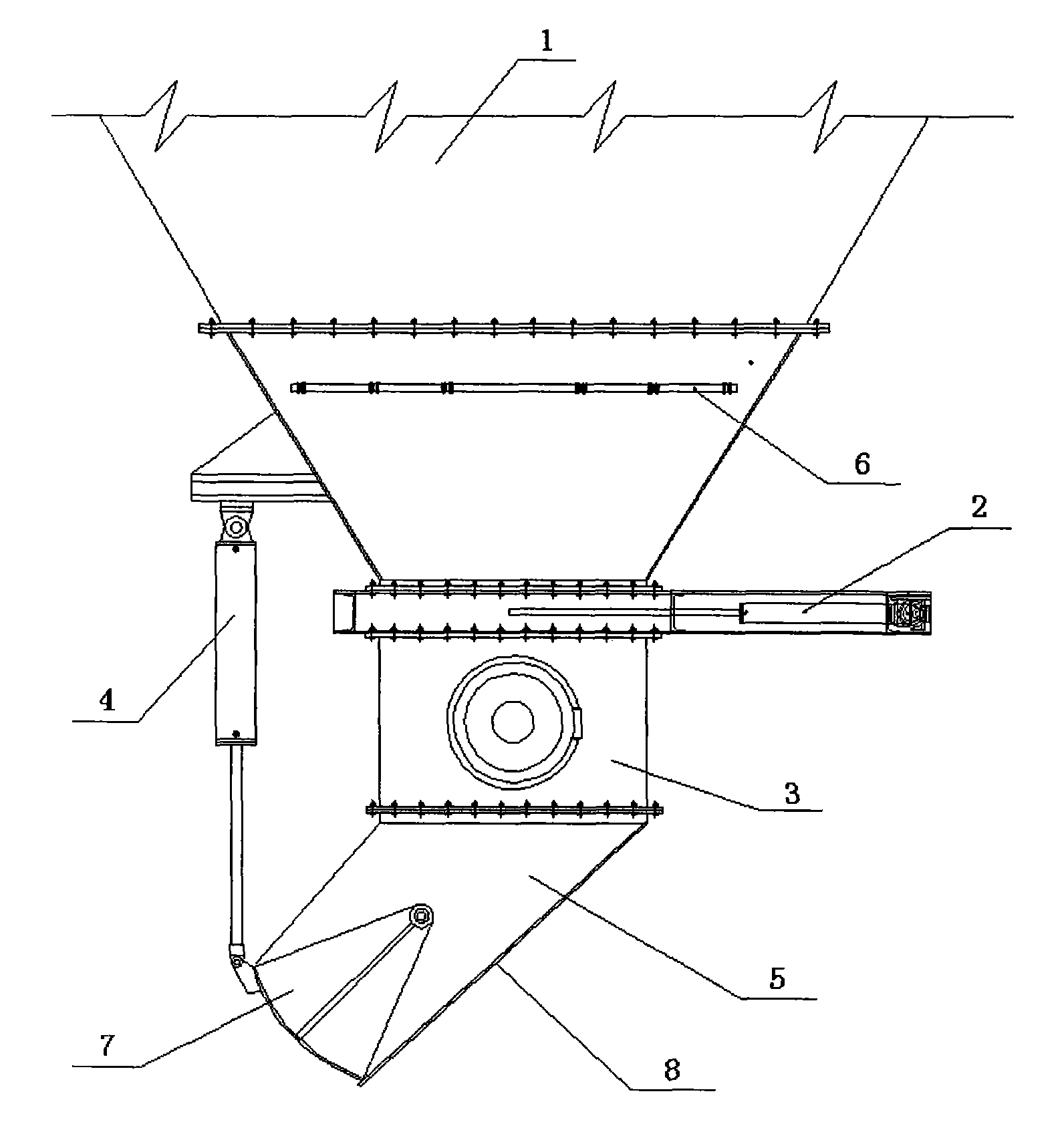
[0018] refer to figure 1 , figure 2 , an electro-hydraulic combined unloading device, comprising a material receiving bin 1, a material volume adjusting device 2, a spiral blanking cylinder 3, an electro-hydraulic push rod 4, a buffer chute cylinder 5, a humidifying and spraying device 6, a sector gate valve 7 and Protective layer 8, the described feed adjustment device is set 2 between the receiving bin 1 and the spiral feeding barrel 3; the described humidifying and spraying device 6 is arranged on the inner wall of the receiving bin 1 and connected The external waterway is connected, and the receiving bin 1 is box-shaped funnel-shaped; the buffer chute tube 5 is connected with the spiral blanking tube 3, and the axis line of the buffer chute tube 5 is connected with the spiral blanking tube ...


PUM


Abstract

The invention discloses an electrical hydraulic combined discharging device which comprises a material receiving bin, a spiral blanking barrel, a material amount adjusting device and a humidifying spraying device, wherein the material amount adjusting device is arranged between the material receiving bin and the blanking barrel; the humidifying spraying device is arranged on the inner wall of the material receiving bin and is communicated with a waterway outside the material receiving bin; and the material receiving bin is in a box type funnel shape. The electrical hydraulic combined discharging device has the advantages that the integral mechanical property is good; the scattering of coal briquettes and the impact on conveying equipment can be avoided to the maximum extent when the coal briquettes are charged and discharged; the working environment is improved, and the work efficiency is enhanced; and the production cost is reduced.

Description

technical field [0001] The invention relates to a discharge device, which belongs to equipment for loading dust materials in vehicle transportation, and is used in industries such as metallurgy, cement, chemical industry, coal and flour. Background technique [0002] At present, in the loading and transportation of powder in metallurgy, cement, chemical, coal and flour industries, since the discharge port of the equipment is fixed, there will be a certain height difference between the discharge hopper of the unloading device and the transportation vehicle. , so in the process of loading and unloading will inevitably produce a lot of dust flying, causing environmental pollution. Of course, the use of humidification can reduce dust, but it will be limited by the application occasion and the environment. For industries such as cement and flour, dust flying will cause waste of resources. As an important energy source, coal has been widely used in various fields. In the process...

Claims


Application Information

Patent Timeline
Patent Type & Authority Applications(China)
IPC IPC(8): B65G67/06B65G69/18B65G47/52
Inventor 高文富高文武魏佑凯
Owner JIANGSU KACHUANG MACHINERY
Why Eureka
Try Eureka