Continuous casting tundish and continuous casting tundish casting control method

A continuous casting tundish and control method technology, applied in the field of tundish, can solve the problems of unfavorable tundish flow field improvement, reduction of molten steel residence time, large amount of residual steel in tundish, etc., to prolong average residence time, reduce The effect of stopping casting

Active Publication Date: 2013-08-14
SHOUGANG CORPORATION
8 Cites 6 Cited by

AI-Extracted Technical Summary

Problems solved by technology

At present, the iron and steel metallurgical slab continuous casting tundish at home and abroad is a two-flow symmetrical tundish, which mainly adopts the flow control method of the combination of turbulent flow controller and retaining wall. It is symmetrical and axisymmetric, but there are certain defects in the flow control combination of turbulence controller + single dam in the two-flow symmetrical tundish used in the past: (1) If the lower retaining wall without holes is used, there are often certain gaps behind the lower retaining wall. The dead zone, and the amount of residual steel in the tundish a...

Method used

[0053] Step 10, the iron sheets blocking the upper two holes of the lower retaining wall 4 are melted, and the molten steel flows out...

Abstract

The invention provides a continuous casting tundish which comprises a second-rate slab continuous casting tundish, a tundish body, a long nozzle 1, a stopper 2, a flow stabilizer 3 and a double retaining wall flow control device. The long nozzle 1 is fixed on the tundish body. The stopper 2 is fixed on the tundish body. The flow stabilizer is located below the long nozzle 1. The double retaining wall flow control device is located between the long nozzle 1 and the stopper 2 and comprises a lower retaining wall 4 and a small retaining dam 5. The small retaining dam 5 is located on the rear side of the lower retaining wall 4. By the continuous casting tundish, liquid surface fluctuating of an flow injection area can be effectively controlled, dead area proportion on the rear side of the lower retaining wall is reduced, tundish casting stoppage is lowered, and average staying time of steel liquid in the tundish is prolonged.

Application Domain

Technology Topic

Staying timeRetaining wall +4

Image

  • Continuous casting tundish and continuous casting tundish casting control method
  • Continuous casting tundish and continuous casting tundish casting control method
  • Continuous casting tundish and continuous casting tundish casting control method

Examples

  • Experimental program(1)

Example Embodiment

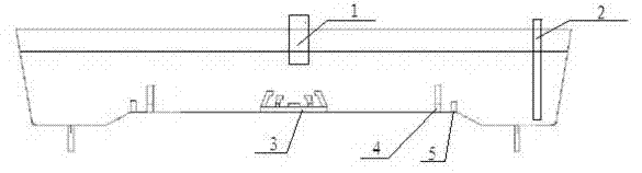
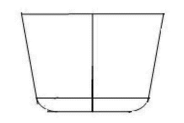
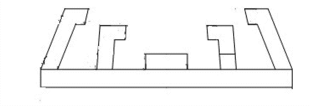
[0028] see Figure 1-4 , a continuous casting tundish provided by an embodiment of the present invention, which includes a two-strand slab continuous casting tundish, and further includes a tundish, a shroud 1, a stopper rod 2, a flow stabilizer 3 and a double retaining wall flow control device. Wherein, the shroud 1 is fixed on the bag body. The stopper rod 2 is fixed on the bag body. The flow stabilizer 3 is located below the shroud 1 . The flow stabilizer 3 is circular with eaves, and there is a double-layer turbulence controller with an inner ring inside. The double retaining wall flow control device is located between the shroud 1 and the stopper rod 2 . The double retaining wall flow control device includes a lower retaining wall 4 and a small retaining dam 5 . Have two apertures on the lower retaining wall 4. Small retaining dam 5 is positioned at lower retaining wall 4 rear sides, and height is slightly higher than the height of the hole that lower retaining wall has. The two-strand slab continuous casting tundish is a two-strand symmetrical tundish. The lining composition of continuous casting tundish is: Tfe%:0.45%~0.6%, SiO 2 %:8.17%~8.78%, Al 2 o 3 %:0.79%~1.48%, Fe 2 o 3 %: 0.24%~0.34%, CaO%: 1.66%~1.71%, MgO%: 79.12%~81.81%, P 2 o 5 %:0.17%~0.29%,TiO 2 %:0.02%~0.05%, C%:0.36%~0.92%.
[0029] The present invention provides an embodiment:
[0030] The optimal position and height of the lower retaining wall are obtained through the following technical scheme.
[0031] A 1:3 water model test was established, and the position and height of the lower retaining wall were optimized for the double-layer turbulence controller and the tundish of the lower retaining wall; Table 1 was obtained. stop time and peak time, etc. The longer the average residence time, the stagnation time and the peak time, the more favorable it is to improve its fluency; the smaller the dead zone ratio, the larger the piston zone ratio, which means it is more conducive to improving its fluency.
[0032] Table 1 Experimental results of different lower retaining wall positions and heights
[0033]
[0034]
[0035] It can be seen from Table 1 that the height of the lower retaining wall is 400mm, and the position is 2000mm away from the long nozzle, which can obviously improve the flow of molten steel in the continuous casting tundish. At this time, the average residence time is 380s, and the proportion of dead zone is reduced to 18.5%.
[0036] The height and position of the optimal small retaining dam are obtained through the following technical scheme.
[0037] Without changing the height and position of the lower retaining wall, a small retaining dam is added on the rear side of the lower retaining wall, and the position and height of the small retaining dam are optimized.
[0038] Table 2 Experimental results of small retaining dams
[0039]
[0040]
[0041] It can be seen from the test results that when the height of the small retaining dam is 150mm and the distance from the lower retaining wall is 160mm, the flow field characteristic parameters are significantly better than other combinations, the stagnation time is extended to 56s, and the dead zone ratio is reduced to 11.5%. Considering the average residence time, dead zone ratio and stagnation time comprehensively, the height of the small retaining dam is 120mm, and the 160mm distance from the lower retaining wall has the second best effect on improving the flow field of the continuous casting tundish, the stagnation time is 45.5s, and the dead zone ratio was 19.6%.
[0042] Before the continuous casting tundish works, the operation steps are as follows:
[0043] Step 1. Install a eaves ring under the long nozzle 1 to form the first turbulence controller;
[0044] Step 2, installing a ring with eaves outside the first turbulence controller formed in step 1 to form a second turbulence controller;
[0045] Step 3, installing an inner ring in the first turbulence controller formed in step 1 to control liquid level fluctuations;
[0046] Step 4. Install the lower retaining wall 4 between the long nozzle 1 and the stopper rod 2, and open two holes on the lower retaining wall 4;
[0047] Step 5, installing a small retaining dam 5 on the rear side of the lower retaining wall 4;
[0048] Step 6. Place iron sheets to block the two holes of the lower retaining wall 4 to prevent molten steel from flowing out when casting begins;
[0049] Step 7. Keep the immersion depth of the long nozzle 1 at 150mm-170mm;
[0050] When the continuous casting tundish works, the operation steps are as follows:
[0051] Step 8. Cast molten steel in the continuous casting tundish at long nozzle 1, control the casting speed at 0.4m/min, and control the weight of the tundish at about 20t;
[0052] Step 9. When the weight of the molten steel in the tundish is 40t, start to add the thermal insulation riser sleeve suitable for the casting. The covering agent is small gray and black particles, non-toxic, tasteless, high calorific value, and has good thermal insulation performance;
[0053] Step 10, the iron sheets blocking the two holes on the lower retaining wall 4 are melted, and the molten steel flows out from the two holes, which reduces the dead area on the rear side of the lower retaining wall and reduces the tundish casting residue.

PUM

no PUM

Description & Claims & Application Information

We can also present the details of the Description, Claims and Application information to help users get a comprehensive understanding of the technical details of the patent, such as background art, summary of invention, brief description of drawings, description of embodiments, and other original content. On the other hand, users can also determine the specific scope of protection of the technology through the list of claims; as well as understand the changes in the life cycle of the technology with the presentation of the patent timeline. Login to view more.

Similar technology patents

Computerized embroidery machine automatic baseline replacing apparatus

InactiveCN103409955AReduce downtimeExtend effective working hoursEmbroidering machines apparatusEngineeringBobbin
Owner:SHANGHAI TALMUD EMBROIDERY MACHINERY

Classification and recommendation of technical efficacy words

Why Eureka
Try Eureka