Hydraulic chuck

A hydraulic and chuck technology, applied in the direction of the chuck, can solve problems such as inaccurate centering

Inactive Publication Date: 2013-08-14
NORTHWESTERN POLYTECHNICAL UNIV
View PDF5 Cites 8 Cited by
  • Summary
  • Abstract
  • Description
  • Claims
  • Application Information

AI Technical Summary

Problems solved by technology

[0005] In order to avoid the deficiencies of the prior art and overcome the problem of inaccurate centering caused by errors caused by positioning errors caused by uneven wear of the gears and threads that drive the jaws during the clamping process of the processing equipment, the present invention proposes a hydraulic Type chuck, the chuck body adopts the structure of the main hydraulic chamber and the auxiliary hydraulic chamber, and the clamping force is transmitted through the hydraulic oil in the hydraulic chamber, so as to realize the clamping of the workpiece by the force movement of the claw and the piston along the guide rail at the same time, and ensure the centering Accuracy; through the spring in the secondary hydraulic chamber, the claws are released after the processing is completed and the hydraulic pressure is released, and the position of the claws is maintained in normal times

Method used


Image

  • Hydraulic chuck
  • Hydraulic chuck
  • Hydraulic chuck

Examples


Embodiment Construction

[0020] This embodiment is a hydraulic chuck.

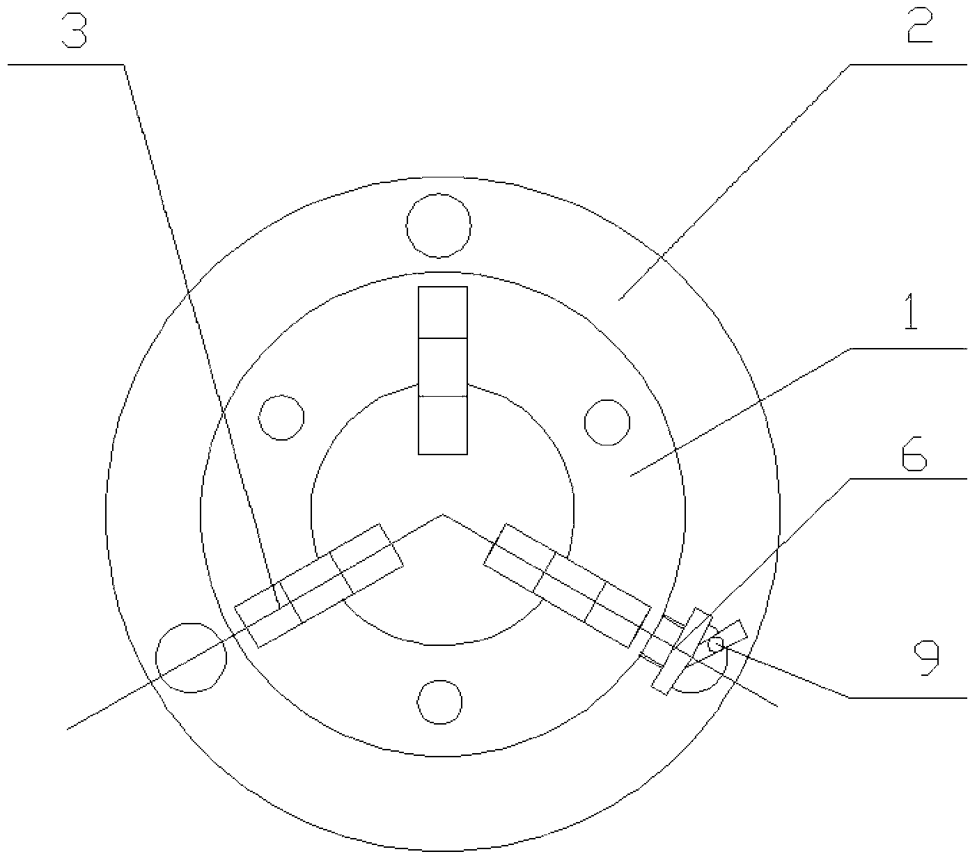
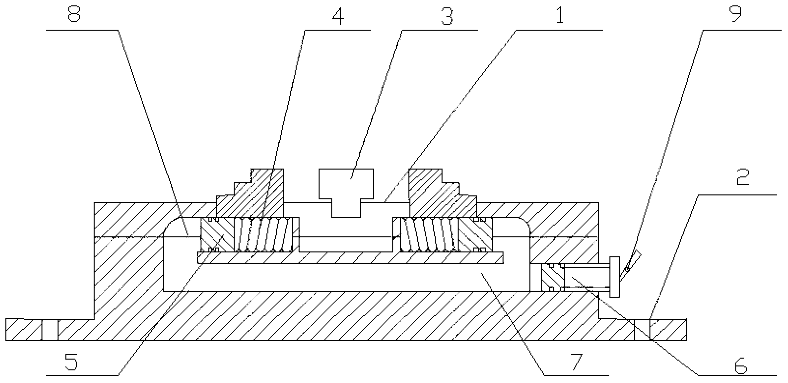
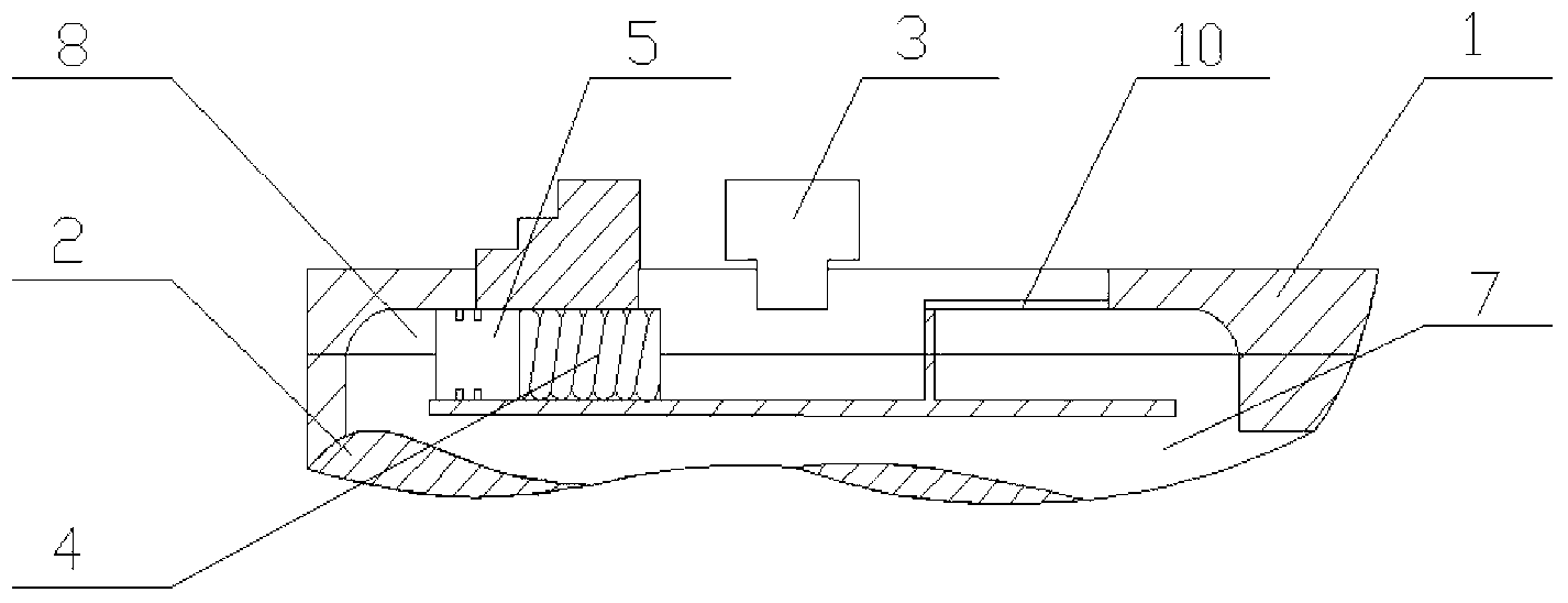
[0021] refer to figure 1 , figure 2 , image 3 , Figure 4 , The hydraulic chuck of the present invention is composed of a chuck body 1, a flange 2, a jaw 3, a spring 4, a piston 5, a pressure nut 6, a main hydraulic chamber 7, an auxiliary hydraulic chamber 8, a wrench 9, and a guide rail 10. The chuck body 1 is fixedly installed in the middle of the flange 2, and is coaxially installed with the flange 2. The chuck body 1 and the flange 2 form a surrounding main hydraulic chamber 7, and the main hydraulic chamber 7 and The three auxiliary hydraulic chambers 8 below the chuck body 1 are connected; the three auxiliary hydraulic chambers 8 are chambers with the same structure and the same size and length. The hydraulic oil injected into the main hydraulic chamber 7 is filled into the three auxiliary hydraulic chambers 8, and the lengths of the three auxiliary hydraulic chambers 8 are consistent to ensure that the piston 5 in ea...


PUM


Abstract

The invention discloses a hydraulic chuck. A chuck body is located in the middle of a flange, a circular main hydraulic cavity is formed by the chuck body and a flange body and is communicated with three auxiliary hydraulic cavities below the chuck body, springs are located in the auxiliary hydraulic cavities, one end of each spring butts against the inner end wall of each auxiliary hydraulic cavity, the other end of each spring is fixedly connected with each piston, the pistons are matched with the auxiliary hydraulic cavities through piston sealing rings, a hydraulic oil injection hole on the outer side of the flange body is communicated with the main hydraulic cavity, a pressing nut is matched with the hydraulic oil injection hole, the front end of the pressing nut is used for fixing a plunger with a sealing ring, and claws are evenly distributed on and fixedly connected with the upper surface of the chuck body with the chuck body as the center. Through clamping force transmitted by hydraulic oil in the main hydraulic cavity and the auxiliary hydraulic cavities, the three claws and the pistons are stressed to move along guide rails simultaneously, and centering accuracy is guaranteed. After processing is finished and hydraulic force is removed, the springs achieve loosening of the claws and keep the positions of the claws at ordinary time. A wrench is installed at the end of the pressing nut and is foldable. The flange is installed on an operation platform of a machine tool.

Description

technical field [0001] The invention belongs to the technical field of mechanical processing and equipment manufacturing, and in particular relates to a hydraulic chuck. Background technique [0002] In the field of metal processing, turning is a commonly used mechanical processing method, mainly used for processing shaft parts. During the turning process, the bar is positioned and clamped synchronously by the three jaws of the chuck. This clamping method makes the cooperation requirements of the three jaws of the three-jaw chuck higher during the clamping process, otherwise the problem of inaccurate positioning will easily occur. The traditional mechanical chuck is prone to uneven wear due to the friction between the driving teeth during use, resulting in inaccurate positioning, which will have a greater impact on machining accuracy. The traditional mechanical three-jaw chuck needs to be tightened with a wrench during the clamping process; during the tightening process, th...

Claims


Application Information

Patent Timeline
Patent Type & Authority Applications(China)
IPC IPC(8): B23B31/16
Inventor 刘维伟万旭生李晓燕王东方陈昊
Owner NORTHWESTERN POLYTECHNICAL UNIV
Why Eureka
Try Eureka