Tray with limiting structure

A technology of limit structure and tray, which is applied in the direction of rigid containers, fragile goods packaging, containers, etc., can solve the problems of COF2 pulling damage, COF damage, mold cost waste, etc., to achieve the effect of expanding compatibility and avoiding pulling

Active Publication Date: 2013-08-14
TCL CHINA STAR OPTOELECTRONICS TECH CO LTD
View PDF6 Cites 6 Cited by
  • Summary
  • Abstract
  • Description
  • Claims
  • Application Information

AI Technical Summary

Problems solved by technology

Open Cells are generally placed flat on the tray, and the positioning device of the tray positions the Open Cell around, because when the Open Cell is subjected to vibration, the PCB board is likely to move with the vibration and pull the COF, resulting in damage to the COF, thus affecting the product quality, and the COF is a flexible sheet, the PCB board is easily brought into two LCD boxes by vibration
In the current Open Cell packaging method, the blister tray is directly formed with columns, such as figure 1 , figure 2 As shown, Open CellA1 has only one COF2, and the tray 4 uses two pillars 5 to block the PCB board 3. This method is only suitable for placing a single tray with a small number of Open Cells. Once the number of Open Cells is large, the pillars 5 will be higher , due to the obstruction of the pillar 5, it is easy to hang the PCB board 3 on the pillar 5 when installing the Open Cell and taking the Open Cell, which will cause the COF2 to be pulled and damaged, which will affect the product quality
The current design of the number of sheets for a single tray is 4 pieces, and this column 5 that has been formed when the tray 4 is produced is not suitable for the commonality of the tray 4. image 3 , if the tray 4 is used to hold the Open Cell B6, the Open Cell B6 has multiple COFs connected to the PCB board 8, and the middle two COF7 will interfere with the two columns 5 of the tray 4, so that the tray 4 cannot be used Install Open Cell B6
Therefore, if you want to install Open Cell B6, you need to re-open a mold for Open Cell B6 to produce the corresponding tray, which causes a waste of mold cost, and this tray is recycled, if not shared, it will cause Waste of packaging resources increases the cost of production

Method used


Image

  • Tray with limiting structure
  • Tray with limiting structure
  • Tray with limiting structure

Examples


Embodiment Construction

[0024] The present invention will be further described below with reference to the accompanying drawings.

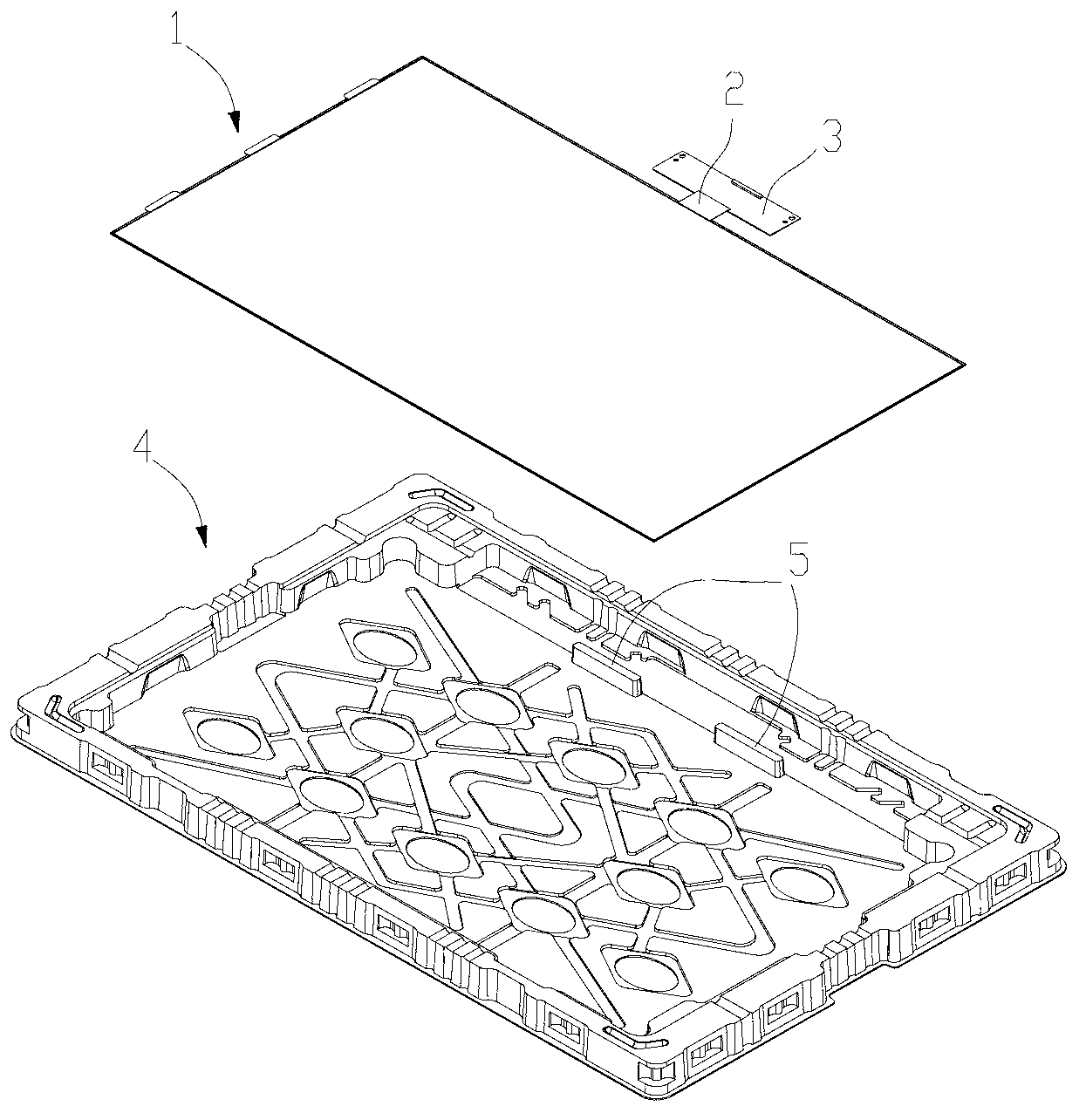
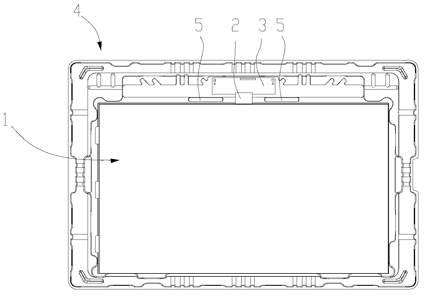
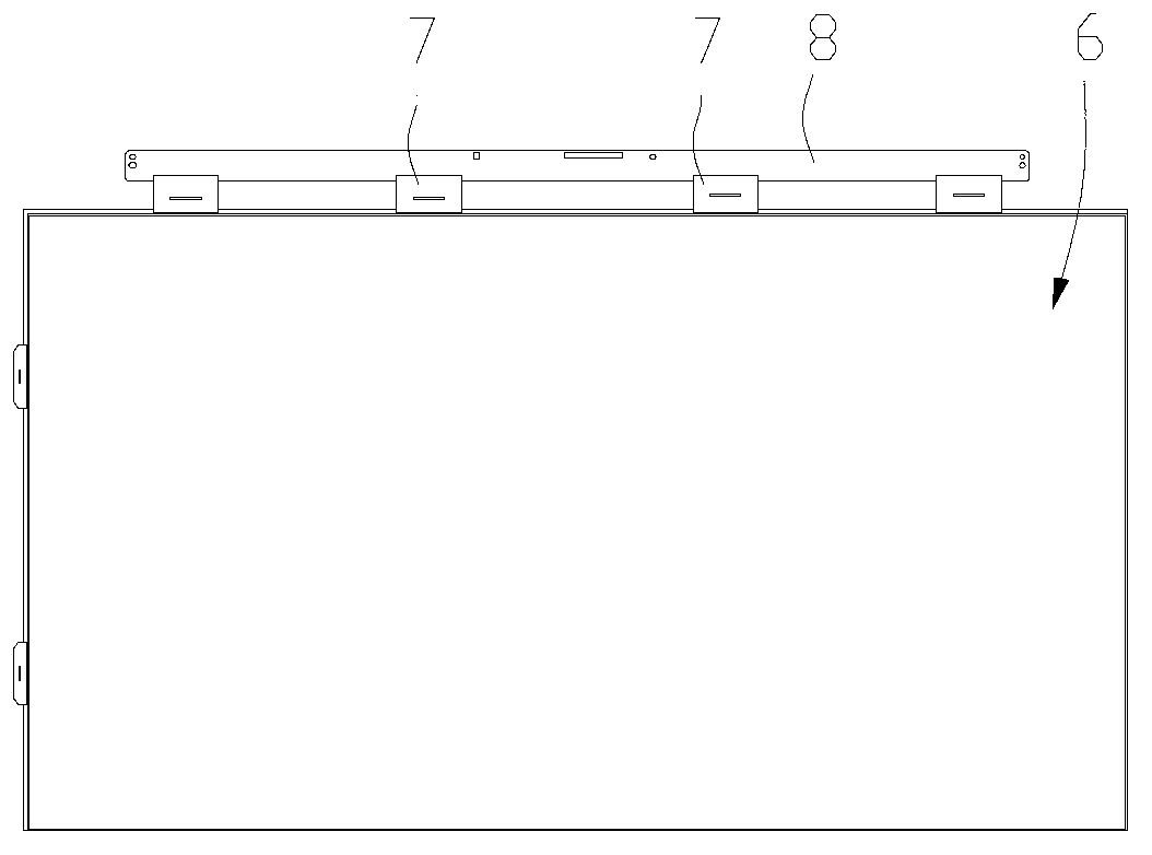
[0025] Such as Figure 4 As shown, the tray for placing the Open Cell of the LCD screen includes a tray body 10, and the tray body 10 is provided with a groove 11 for placing the Open Cell, and the groove 11 is used for placing the Open Cell. Also includes limit assembly 30, see also Figure 5 , the limit assembly 30 is fixed on the body bottom plate 12 of the gap between the PCB board 23 and the liquid crystal box 22 of the Open CellA 20 (see Figure 7 , Figure 8 ), the limit assembly 30 is composed of a limit frame 31 and a limit block 32 in the limit frame, see Image 6 , wherein the limit frame 31 is in the shape of a "several", two ends are two feet 311 extending to both sides, and are on the same plane, and an adhesive layer 40 is provided at the bottom of the two feet 311 of the limit frame 31, which is adhered to the tray body On the bottom plate 12, when th...


PUM


Abstract

A tray with a limiting structure is used for packaging an Open Cell of a liquid crystal screen and comprises a tray body. A groove for placing the Open Cell is arranged in the tray body. The tray is characterized by further comprising a limiting assembly, and the limiting assembly is connected to a body base plate of a gap between a printed circuit board (PCB) of the Open Cell and a liquid crystal box. The limiting assembly is connected with the tray body, and can be installed when in need or can be taken down when not in need, tray using compatibility is expanded, and the packaging requirements of an Open Cell A and an Open Cell B are met. The position of a limiting block in the limiting assembly is adjustable simultaneously and pull between the Open Cell and the limiting assembly is effectively avoided.

Description

technical field [0001] The invention relates to a tray for placing an Open Cell of a liquid crystal screen, in particular to a tray with a position-limiting structure. Background technique [0002] At present, the panel industry has a variety of packaging methods for LCD panels, including blister trays, injection molded boxes, and foamed products; liquid crystal panels have two types: The industry defines them as Cell and Open Cell respectively. Cell is a liquid crystal box formed by sandwiching a liquid crystal seal between two glass substrates. Its appearance is the same as that of ordinary thin glass. Open Cell is equipped with various interfaces on the basis of Cell. , so as to connect an external signal source, etc., but the Open Cell does not include the backlight, frame and other components in the liquid crystal module (LCM, liquid crystal module). [0003] Usually, Open Cell connects more than one PCB board through a flexible sheet. This flexible sheet is called COF...

Claims


Application Information

Patent Timeline
Patent Type & Authority Applications(China)
IPC IPC(8): B65D85/30B65D81/107B65D19/02B65D19/38
CPCB65D85/48
Inventor 胡乾双
Owner TCL CHINA STAR OPTOELECTRONICS TECH CO LTD
Why Eureka
Try Eureka