
Yarn feeder and yarn brake

A yarn brake and yarn supply technology, which is applied in textiles, papermaking, looms, knitting, etc., can solve the problems of uncontrollability and affecting the braking effect, and achieve the effect of eliminating vibration and maintaining yarn braking performance

Active Publication Date: 2015-04-01
VANDEWIELE SWEDEN AB
View PDF11 Cites 0 Cited by
  • Summary
  • Abstract
  • Description
  • Claims
  • Application Information

AI Technical Summary

Problems solved by technology

Worst case, the entire brake band would be lifted from the pull-out edge by these resonances, thus affecting the braking effect on the yarn in an uncontrollable way

Method used


Image

  • Yarn feeder and yarn brake
  • Yarn feeder and yarn brake
  • Yarn feeder and yarn brake

Examples


Embodiment Construction

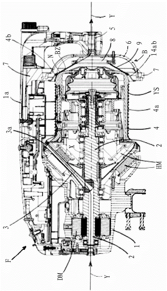
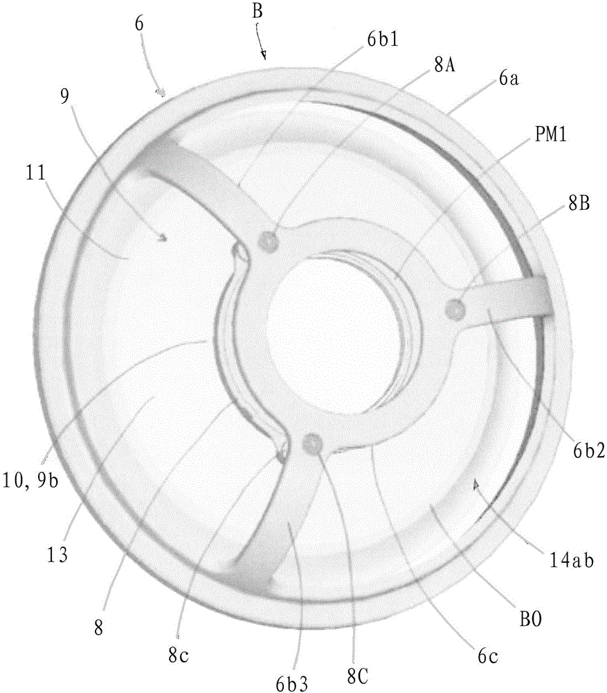
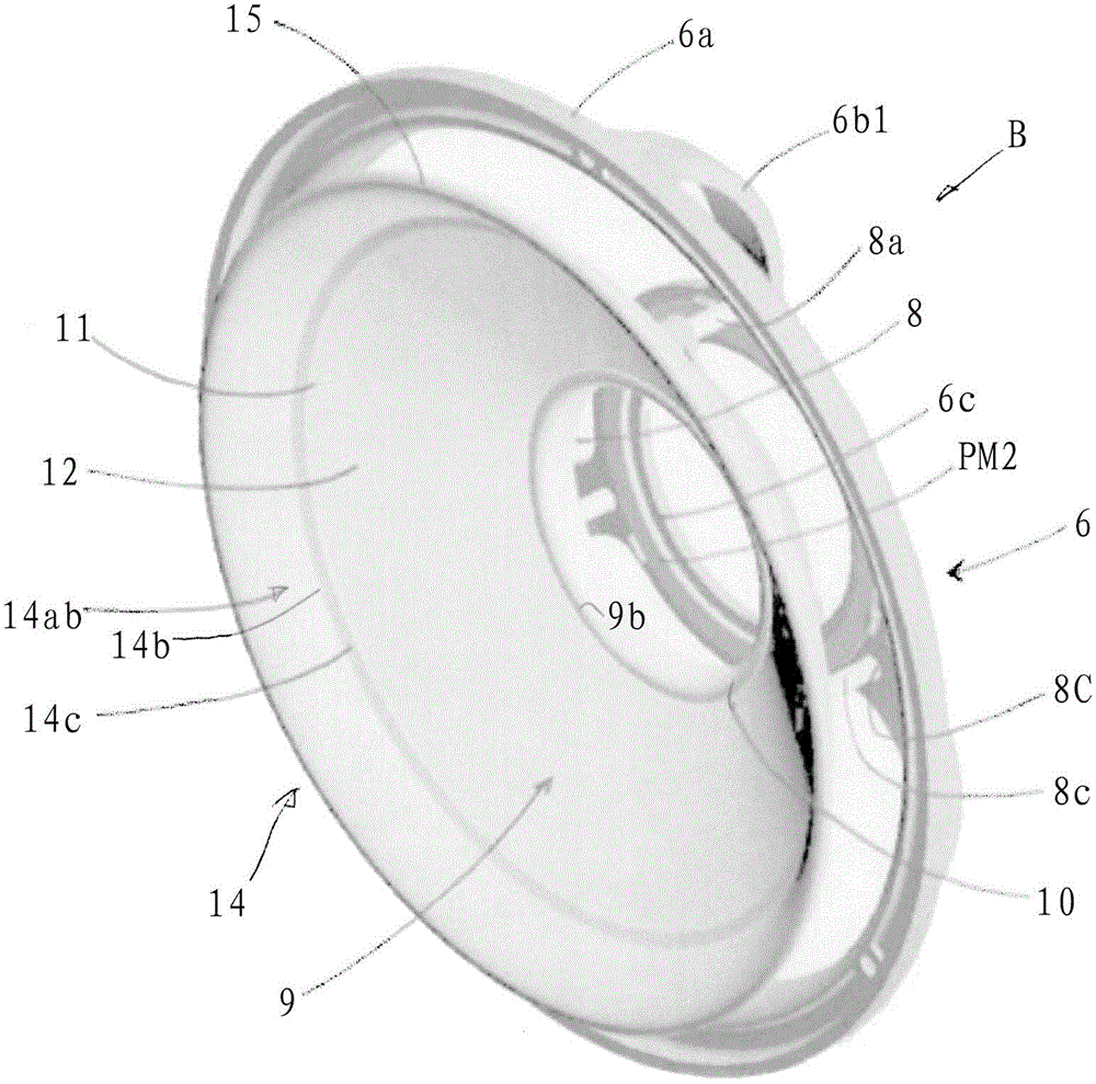
[0031] figure 1 A yarn feeder F with a stationary housing 1 is shown, comprising a drive motor DM for driving a central shaft 2 in rotation within the housing 1 . The upstream rear part of the shaft 2 is hollow and communicates with the yarn winding tube 3 extending obliquely outwards, the yarn winding tube 3 is fixed to the middle part of the shaft 2, and the yarn winding tube 3 rotates together with the shaft 2 . A storage body 4 is rotatably supported in front of the shaft 2 . The storage body 4 is prevented from co-rotating with the shaft 2 when the shaft 2 is driven, for example in cooperation with the permanent magnets HM arranged in the storage body 4 and the stationary housing 1 respectively. The storage body 4 defines a substantially cylindrical storage surface 4a and has an axis X. As shown in FIG. The storage surface 4a serves to support a schematically shown temporary yarn storage YS formed from a plurality of coils of yarn Y wound continuously. For example, the...


PUM


Abstract

A yarn feeder (F), comprising a storage body (4) with a withdrawal rim (4b), a yarn brake (B) including a hollow frusto-cone body (9), deformable in radial direction but essentially stiff in axial direction and resiliently forced against the withdrawal rim (4b) coaxially with an axis (X) of the storage body (4), and a substantially annular oscillation damper (14) associated with the frusto-cone body (9) as a counter-mass damper suppressing oscillations of the frusto-cone body (9), and a yarn brake (B) for yarn feeders (F).

Description

technical field [0001] The invention relates to a yarn feeder and a yarn brake. Background technique [0002] One of several variant types of yarn brakes for yarn feeders is disclosed by EP2213776A1. It is known that the frusto-cone of the yarn brake consists of a high-performance thermoplastic polymer such as polyketone. The known yarn brake is a constructional unit and can be integrated into the yarn feeder. Known yarn brakes have proven to have excellent properties since their introduction into the textile field, for example in terms of wear resistance and good yarn tension properties. However, experience in the textile field in recent years has shown that for certain types of yarns, i.e. rough and / or harder yarns, such as rough cotton, chenille or similar unmanageable or fragile yarns, in order to achieve In order to optimize the performance of the yarn brake, further improvement of the yarn brake is still needed. [0003] Essentially it is important to ensure the sa...

Claims


Application Information

Patent Timeline
Patent Type & Authority Patents(China)
IPC IPC(8): D03D47/36D04B15/48D04B27/10
CPCD03D47/366D04B15/484
Inventor T·贝里曼
Owner VANDEWIELE SWEDEN AB
Learn More