Quickly-clamped concrete pouring device
A concrete and clamping technology, which is used in construction, building structure, and on-site preparation of building components, can solve the problems of low turnover of formwork, low connection strength, time-consuming connection and disassembly, and improve the efficiency of formwork assembly and disassembly. , The effect of high repetition rate and rapid installation
- Summary
- Abstract
- Description
- Claims
- Application Information
AI Technical Summary
Problems solved by technology
Method used
Image
Examples
Embodiment 1
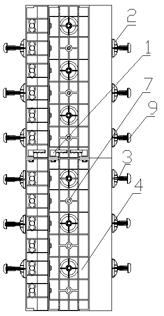
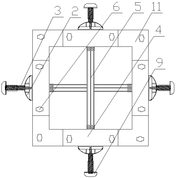
[0026] Embodiment 1: as figure 1 , figure 2 , Figure 6 The quick clamping concrete pouring device shown is used for the pouring construction of column concrete. Each layer of the concrete pouring device has four curved building formworks 11 located at the four corners; each of the four sides has one piece connected between the two curved building formworks 11 A flat plate building formwork 4; a plurality of screw rods 3; a plurality of support tubes 5 with a hollow inner cavity; a plurality of screw disks 2, and adjacent building formworks are detachably connected together. Both the curved building formwork 11 and the flat building formwork 4 are formed by injection molding of a mixture of 85 parts by weight of polypropylene and 15 parts by weight of glass fiber. It has criss-cross reinforcing ribs, wherein the reinforcing ribs on the edge of the main board have several waist-shaped through holes 6, and the middle part of the flat building formwork 4 has tapered through ho...
Embodiment 2
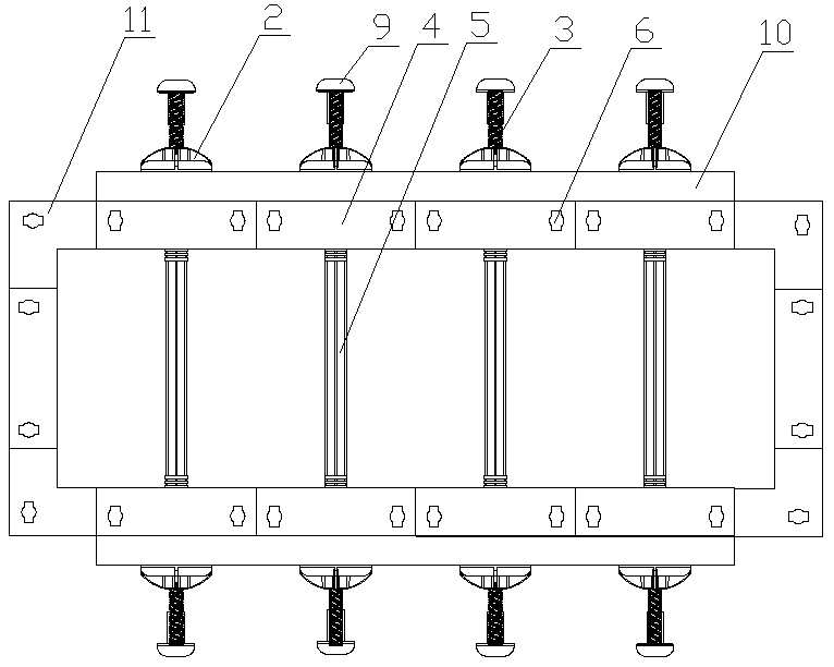
[0027] Embodiment 2: as image 3 , Figure 5The quick clamping concrete pouring device shown is used for concrete pouring construction. Each layer of the concrete pouring device has four curved building templates 11 located at the four corners; each of the two short sides has a piece connected between the two curved building templates 11 The flat building formwork 4 between the two long sides each has a plurality of flat building formworks 4; a plurality of screw rods 3; a plurality of support tubes 5 with a hollow inner cavity; a plurality of screw disks 2, and the adjacent building formwork connected. Both the curved building formwork 11 and the flat building formwork 4 are formed by injection molding of 80 parts by weight of polyethylene and 20 parts by weight of glass fiber mixture. There are criss-cross ribs, wherein one of the ribs on the left and right edges of the main body plate has a plurality of bolts 13, and the ribs on the opposite edge have jacks 12 that match ...
Embodiment 3
[0028] Embodiment 3: as Figure 4 , Figure 7 The quick clamping concrete pouring device shown is used for concrete pouring construction. Each layer of the concrete pouring device has a semi-circular curved building formwork 11; two long sides respectively have a plurality of flat plate building formwork 4; a plurality of screw rods 3 ; A plurality of support tubes 5 with a hollow cavity; a plurality of spiral discs 2, detachably connected together between adjacent building templates. Both the curved building formwork 11 and the flat building formwork 4 are formed by injection molding of 90 parts by weight of ABS resin and 10 parts by weight of a glass fiber mixture. It has criss-cross reinforcing ribs, wherein one of the reinforcing ribs on the left and right edges of the main body panel has at least one insertion groove 15, and the opposite edge reinforcing rib has an insertion protrusion that matches the insertion groove 15. Platform 14 ; two adjacent building formworks a...
PUM
 Abstract
Description
Claims
Application Information
 - R&D
- Intellectual Property
- Life Sciences
- Materials
- Tech Scout
- Unparalleled Data Quality
- Higher Quality Content
- 60% Fewer Hallucinations
Browse by: Latest US Patents, China's latest patents, Technical Efficacy Thesaurus, Application Domain, Technology Topic, Popular Technical Reports.
© 2025 PatSnap. All rights reserved.Legal|Privacy policy|Modern Slavery Act Transparency Statement|Sitemap|About US| Contact US: help@patsnap.com


