Engine

An engine and tight ring technology, applied in the direction of engine components, machines/engines, mechanical equipment, etc., can solve the problem of not preventing the valve stem and valve guide from accelerated wear and valve hovering, manual removal, and the engine cannot automatically remove the valve stem. Carbon and other issues can be reduced to reduce valve hovering and reduce accelerated wear

Active Publication Date: 2013-08-14
CHINA HANGFA SOUTH IND CO LTD
View PDF6 Cites 0 Cited by
  • Summary
  • Abstract
  • Description
  • Claims
  • Application Information

AI Technical Summary

Problems solved by technology

[0004] Although the above methods can reduce the generation of carbon deposits, if the valve stems have carbon deposits, they cannot be removed automatically and must be removed manually when the engine is repaired.
Therefore, the engine of the prior art cannot automatically remove the carbon deposits on the valve stems, and thus cannot prevent the accelerated wear and valve hovering of the valve stems and valve guides caused by carbon deposits and gelling.

Method used


Image

  • Engine
  • Engine
  • Engine

Examples


Embodiment Construction

[0032] Hereinafter, the present invention will be described in detail with reference to the drawings and in conjunction with the embodiments. It should be noted that the embodiments in the application and the features in the embodiments can be combined with each other if there is no conflict.

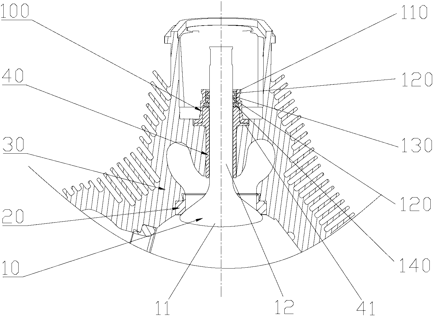
[0033] figure 1 It is a schematic diagram of the matching structure of the valve stem carbon scraping device, the valve and the valve guide of the engine according to an embodiment of the present invention. in figure 1 In the figure, only the valve 10, the valve seat 20, a part of the body 30, the valve guide 40 and the valve stem carbon scraping device 100 are shown.

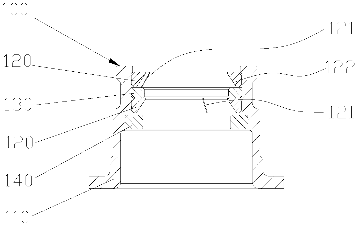
[0034] Such as figure 1 As shown, the engine of this embodiment includes a valve 10, a valve guide 40, and a valve stem carbon deposit scraping device 100. The valve 10 includes a head 11 and a valve stem 12 that is clearance fit with the valve guide 40. The valve stem carbon deposit scraping device 100 includes a rigid sea...


PUM


Abstract

The invention provides an engine which comprises an air valve (10) and a valve guide pipe (40); the air valve (10) comprises a head (11) and an air valve rod (12) which is matched with the valve guide pipe (40) in a clearance mode; the engine also comprises an air valve rod carbon deposition scraping device (100) and a limitation device; the air valve rod carbon deposition scraping device (100) comprises a rigid seal ring (120); one end of the valve guide pipe (40), which is far away from the head (11), is provided with the rigid seal ring (120) and the rigid seal ring (120) is sleeved on the air valve rod (12); a radial inner surface of the rigid seal ring (120) is provided with a cooperation portion which is matched with the periphery face of the air valve rod (12) in a clearance mode; the limitation device is fixedly arranged relative to the valve guide pipe (40); and the limitation device acts on the rigid seal ring (120) to restrict axial motion of the rigid seal ring (120) relative to the valve guide pipe (40). The engine has the advantage of being capable of effectively reducing accelerated abrasion of the air valve rod and the valve guide pipe and hovering of the air valve due to carbon disposition and gum disposition.

Description

Technical field [0001] The present invention relates to the field of power machinery, and more specifically, to an engine. Background technique [0002] When a piston engine is working, sufficient lubrication is required between the valve stem and the valve guide. Lubricating oil will inevitably enter the combustion chamber through the gap between the valve stem and the valve guide, causing carbon deposits on the valve stem and head of the valve. If the valve stem and the valve guide are carbonized and glued, it will accelerate the wear of the valve stem and the valve guide, and even cause the valve stem to block in the valve guide and cause the valve to hover. [0003] In the prior art, in order to reduce the occurrence of carbon deposits on the valve stem, the fitting clearance between the valve stem and the valve guide is usually reduced to control the amount of oil entering the fitting clearance. In some engines, a rubber oil baffle is placed on the upper end of the valve guid...

Claims


Application Information

Patent Timeline
Patent Type & Authority Applications(China)
IPC IPC(8): F01L3/24
Inventor 甘安唐武杰黄智格周智健
Owner CHINA HANGFA SOUTH IND CO LTD
Why Eureka
Try Eureka