Turbocharger bearing body assembly

A turbocharger and bearing body technology, applied in engine components, machines/engines, mechanical equipment, etc., can solve the problems of increasing the peripheral installation of the engine, high cost, complex structure and assembly, and achieve the effect of reducing the temperature

Pending Publication Date: 2018-04-03
HUNAN TYEN MACHINERY
View PDF2 Cites 5 Cited by
  • Summary
  • Abstract
  • Description
  • Claims
  • Application Information

AI Technical Summary

Problems solved by technology

Chinese patent ZL201320805367.1 discloses a "turbocharger water-cooled bearing body". The bearing body is provided with a cooling water cavity, and the cooling water in the cooling water cavity is cooled with lubricating oil. This structure can effectively reduce the turbocharger turbine. The temperature of the end seal ring and the floating bearing at the turbine end, but this structure needs to introduce external cooling medium water, increase the peripheral installation of the engine, the structure and assembly are complicated, and the cost is high, which affects its wide application in turbochargers
Chinese patent ZL2...

Method used


Image

  • Turbocharger bearing body assembly
  • Turbocharger bearing body assembly
  • Turbocharger bearing body assembly

Examples


Embodiment 1

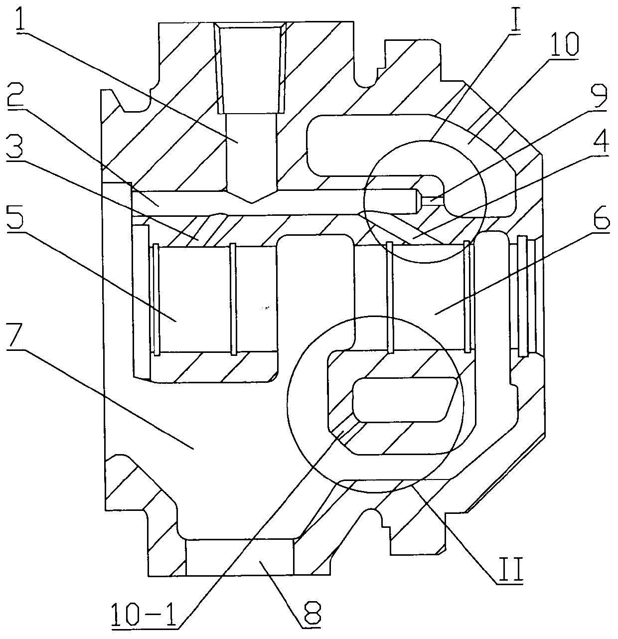
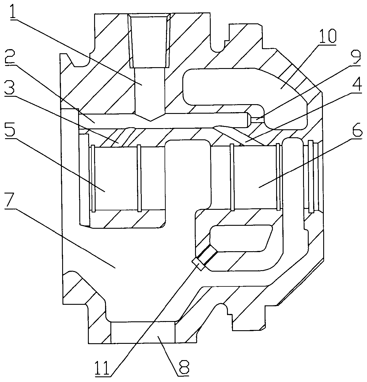
[0028] Embodiment 1. The turbocharger bearing body assembly. The bearing body is provided with an oil inlet hole 1, a main oil hole 2, an inclined oil guide hole 3 at the compressor end, an inclined oil guide hole 4 at the turbine end, and a floating bearing hole 5 at the compressor end. The floating bearing hole 6 at the turbine end, the main oil chamber 7 and the oil outlet hole 8, the oil inlet hole 1 communicates with the main oil hole 2, and one end of the inclined oil hole 3 at the compressor end and one end of the inclined oil hole 4 at the turbine end are connected to the main oil hole 4 respectively. The oil hole 2 communicates, the other end of the oil guide hole 3 at the compressor end and the other end of the oil guide hole 4 at the turbine end respectively communicate with the compressor end floating bearing hole 5 and the turbine end floating bearing hole 6, and the compressor end floating bearing hole 5 and The floating bearing holes 6 at the turbine end communic...

Embodiment 2

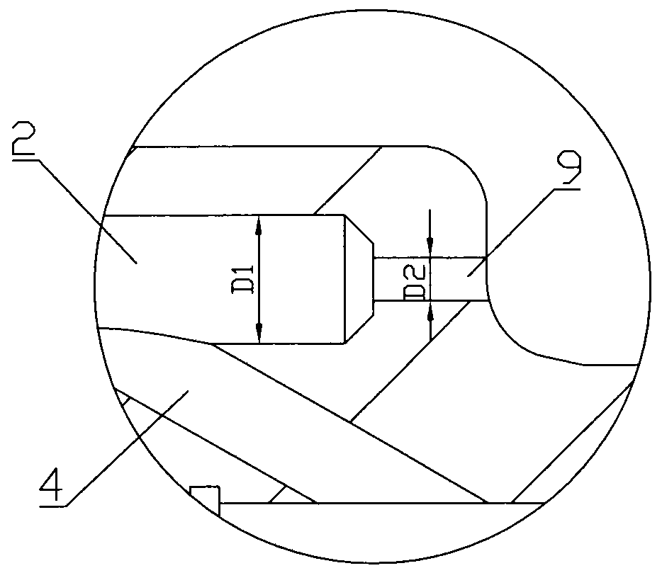
[0037] Embodiment 2. The difference between this embodiment and Embodiment 1 is that in this embodiment, the ratio of D1 to D2 is 1:0.3, and the ratio of D2 to D3 is 1:1.05.

Embodiment 3

[0038] Embodiment 3. The difference between this embodiment and Embodiment 1 is that in this embodiment, the ratio of D1 to D2 is 1:0.4, and the ratio of D2 to D3 is 1:1.1.


PUM


Abstract

Turbocharger bearing body assembly, the bearing body is equipped with oil inlet hole, main oil hole, oil guide hole at the compressor end, oil guide hole at the turbine end, floating bearing hole at the compressor end, floating bearing hole at the turbine end, main oil chamber and oil outlet. An independent cooling oil chamber is arranged at the turbine end of the bearing body, and the cooling oil chamber runs through the upper and lower structures of the turbine end of the bearing body. An oil injection hole is arranged at the turbine end of the main oil hole, and the oil injection hole communicates with an independent cooling oil chamber. A lubricating oil pressure relief hole is provided at the bottom of the independent cooling oil chamber close to the oil outlet, and the pressure relief hole communicates with the main oil chamber, so that the lubricating oil in the cooling oil chamber can be discharged to the main oil chamber in time.

Description

technical field [0001] The invention relates to the technical field of turbochargers, in particular to a turbocharger bearing assembly used on the turbocharger and capable of improving cooling effect. Background technique [0002] With the continuous improvement of internal combustion engine strengthening and increasingly stringent emission standards, turbocharging technology has become one of the most critical measures to improve the economy, power and emission standards of internal combustion engines. With the development of diesel and gas engine turbocharging technology, the exhaust gas temperature it bears is also increasing. Since the sealing ring and bearing system are the weak links in the structure of the turbocharger, it has a great impact on the reliability of the turbocharger, and even Work efficiency has a very important impact. [0003] Existing turbocharger bearing body as attached Figure 5 As shown, the bearing body is provided with oil inlet hole 1, main oi...

Claims


Application Information

Patent Timeline
IPC IPC(8): F01D25/16F01D25/12F01D25/18
CPCF01D25/125F01D25/16F01D25/18
Inventor 程云荣徐晓波张华达赵佳胡奇刘石源周成尧
Owner HUNAN TYEN MACHINERY
Why Eureka
Try Eureka