
Air conditioner

A technology of air conditioners and heat exchangers, which is applied in space heating and ventilation details, household heating, lighting and heating equipment, etc. It can solve the problems of simultaneous two-way or multi-directional air outlets, high material costs, and cross-flow fans. Performance degradation and other issues

Active Publication Date: 2013-08-14
SUZHOU SAMSUNG ELECTRONICS CO LTD
View PDF6 Cites 14 Cited by
  • Summary
  • Abstract
  • Description
  • Claims
  • Application Information

AI Technical Summary

Problems solved by technology

Among them, the use of two or more cross-flow fans for air supply requires a corresponding number of motors, and the material cost is relatively high; the use of specially designed blades for air supply requires changing the direction of rotation to change the direction of the air outlet, which cannot be achieved simultaneously. Two-way or multi-directional airflow, and whether the cross-flow fan is running forward or reverse, the performance of the cross-flow fan is significantly reduced. At present, there is no fan duct that uses a unidirectional rotating cross-flow fan to simultaneously achieve two-way or multi-directional airflow. design

Method used


Image

  • Air conditioner
  • Air conditioner
  • Air conditioner

Examples


Embodiment 1

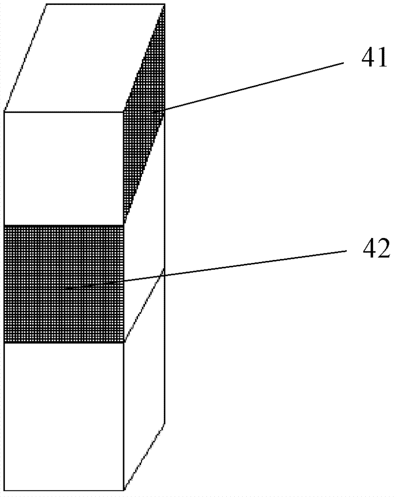
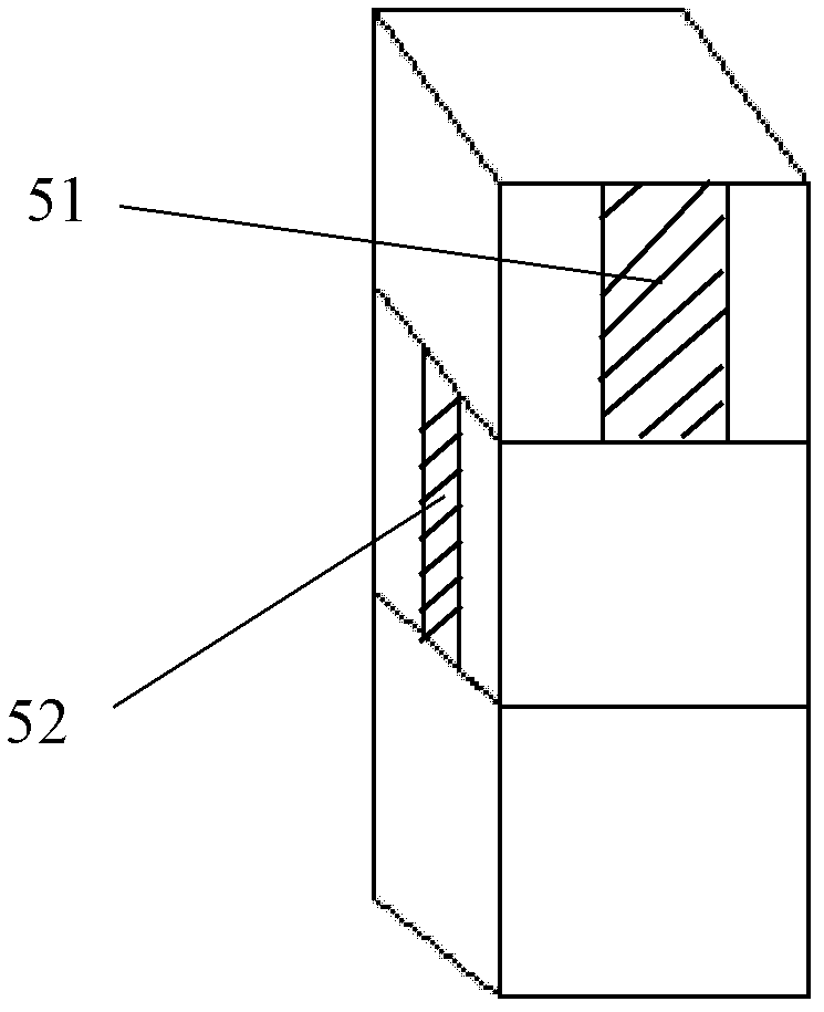
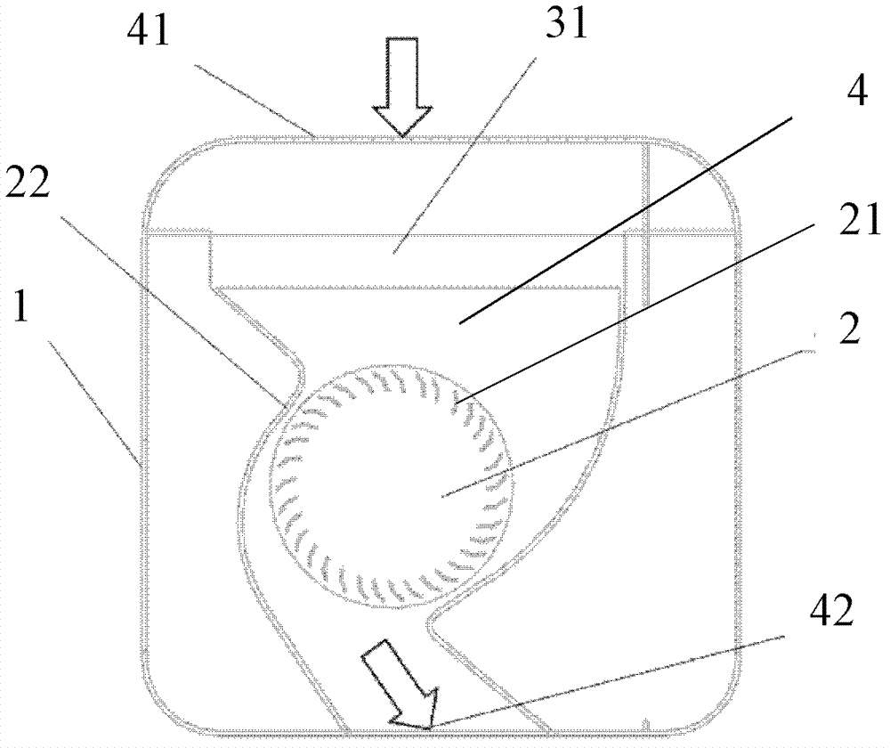
[0034] see Figure 1 to Figure 5 As shown, the air conditioner according to the first embodiment of the present invention includes an air conditioner casing 1 , a cross-flow fan 2 , a heat exchanger, and a driving motor for driving the cross-flow fan 2 to rotate. The cross-flow fan 2 includes an impeller 21 and a volute sleeved on the outside of the impeller 21 to guide air flow. The volute includes two volutes, namely a first volute 22 and a second volute 23 which are independently formed and movably connected to each other. The cross-flow fan 2 also includes a first cross-flow air duct 4 that guides the air flow of the first volute 22 and a second cross-flow air duct 5 that guides the air flow of the second volute 23. The first cross-flow air duct 4 is provided with a first air duct The air inlet 41 and the air outlet 42 of the first air channel, the second cross-flow air channel 5 is provided with the air inlet 51 of the second air channel and the air outlet 52 of the seco...

Embodiment 2

[0042] see Figure 6 As shown, the air conditioner according to the second embodiment of the present invention includes an air conditioner housing 14 , a cross-flow fan 6 , a heat exchanger, and a driving motor for driving the cross-flow fan 6 to rotate. The cross-flow fan 6 includes an impeller and a volute sleeved on the outside of the impeller to guide the flow of air. The volutes include three, and the three volutes are respectively the first volute 7 and the second volute which are independently formed and movably connected to each other. Shell 8 and the third volute 9. The cross-flow fan 6 also includes a first cross-flow air passage 71 for guiding the air flow of the first volute 7, a second cross-flow air passage 81 for guiding the air flow of the second volute 8, and a third passage for guiding the air flow of the third volute 9. Airway 91. The first cross-flow air duct 71 is provided with a first air duct air inlet 711 and a first air duct air outlet 712, and the s...


PUM


Abstract

An air conditioner comprises a tubular fan, a heat exchanger and a driving motor for driving the tubular fan to rotate. The tubular fan has two or more than two tubular air channels, each tubular air channel is provided with an air outlet, and the two or more than two tubular air channels share the tubular fan and are axially and parallelly distributed along the tubular fan. The plurality of tubular air channels share the tubular fan, the shape of blades of the fan does not need to be specially designed, the multifunctional air outlet function can be achieved by enabling one tubular fan to rotate in the single direction, and the rotating angle of the plurality of tubular air channels can be changed according to requirements so as to achieve an optimum air feeding mode.

Description

technical field [0001] The invention relates to the field of air conditioning, in particular to an air conditioner capable of blowing air in two or more directions at the same time. Background technique [0002] Cross-flow fans generally use a relatively long barrel-shaped fan impeller to work, and the blades are long, which can use a relatively low speed on the basis of ensuring the overall air circulation. The impeller in the cross-flow fan is generally a multi-blade blade type, but the two end faces are closed, and the width of the impeller is not limited. When the width increases, the flow rate also increases. Unlike the centrifugal fan, the cross-flow fan is opened on the side plate of the casing so that the airflow enters the fan axially, but the casing is partially opened so that the airflow directly enters the fan radially. Some cross-flow fans add fixed guide vanes to the inner edge of the impeller to improve the airflow state. The cross-flow fan has the character...

Claims


Application Information

Patent Timeline
Patent Type & Authority Applications(China)
IPC IPC(8): F24F13/00
Inventor 奇玉文
Owner SUZHOU SAMSUNG ELECTRONICS CO LTD
Learn More