Lightning induction voltage determining method and system on distributing lines

A technology of lightning induction and determination method, applied in the field of power grid, can solve the problem of inability to achieve accurate analysis of lightning-induced overvoltage in distribution lines, and achieve the effect of achieving accurate analysis and improving accuracy

Active Publication Date: 2013-08-14
GUANGZHOU POWER SUPPLY CO LTD +1
View PDF1 Cites 18 Cited by
  • Summary
  • Abstract
  • Description
  • Claims
  • Application Information

AI Technical Summary

Problems solved by technology

[0004] In the existing theories of lightning-induced overvoltage generation, they only describe the generation of lightn...

Method used


Image

  • Lightning induction voltage determining method and system on distributing lines
  • Lightning induction voltage determining method and system on distributing lines
  • Lightning induction voltage determining method and system on distributing lines

Examples


Embodiment 1

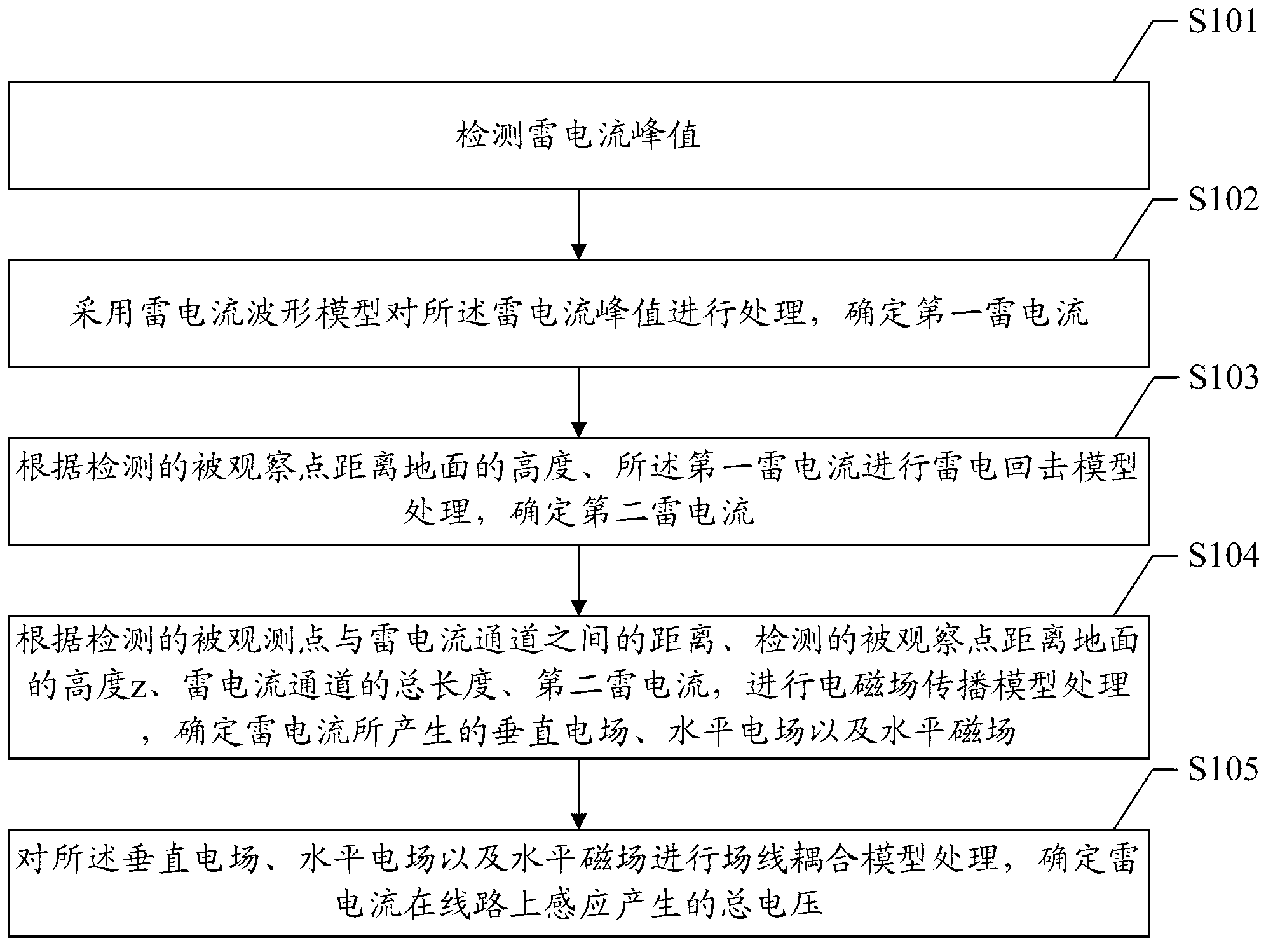
[0026] figure 1 A schematic flowchart of Embodiment 1 of the method for determining the lightning-induced voltage of a distribution line according to the present invention is shown in . exist figure 1 In the illustration, the influence of the precursor development process is not considered as an example for illustration.

[0027] Such as figure 1 As shown, the method in the first embodiment includes steps:

[0028] Step S101: detecting the peak value of the lightning current;

[0029] Step S102: using the lightning current waveform model to process the peak value of the lightning current to determine the first lightning current i(t);

[0030] Step S103: According to the detected height z of the observed point from the ground and the first lightning current i(t), perform lightning return model processing to determine the second lightning current i(z,t);

[0031] Step S104: According to the detected distance r between the observed point and the lightning current channel, th...

Embodiment 2

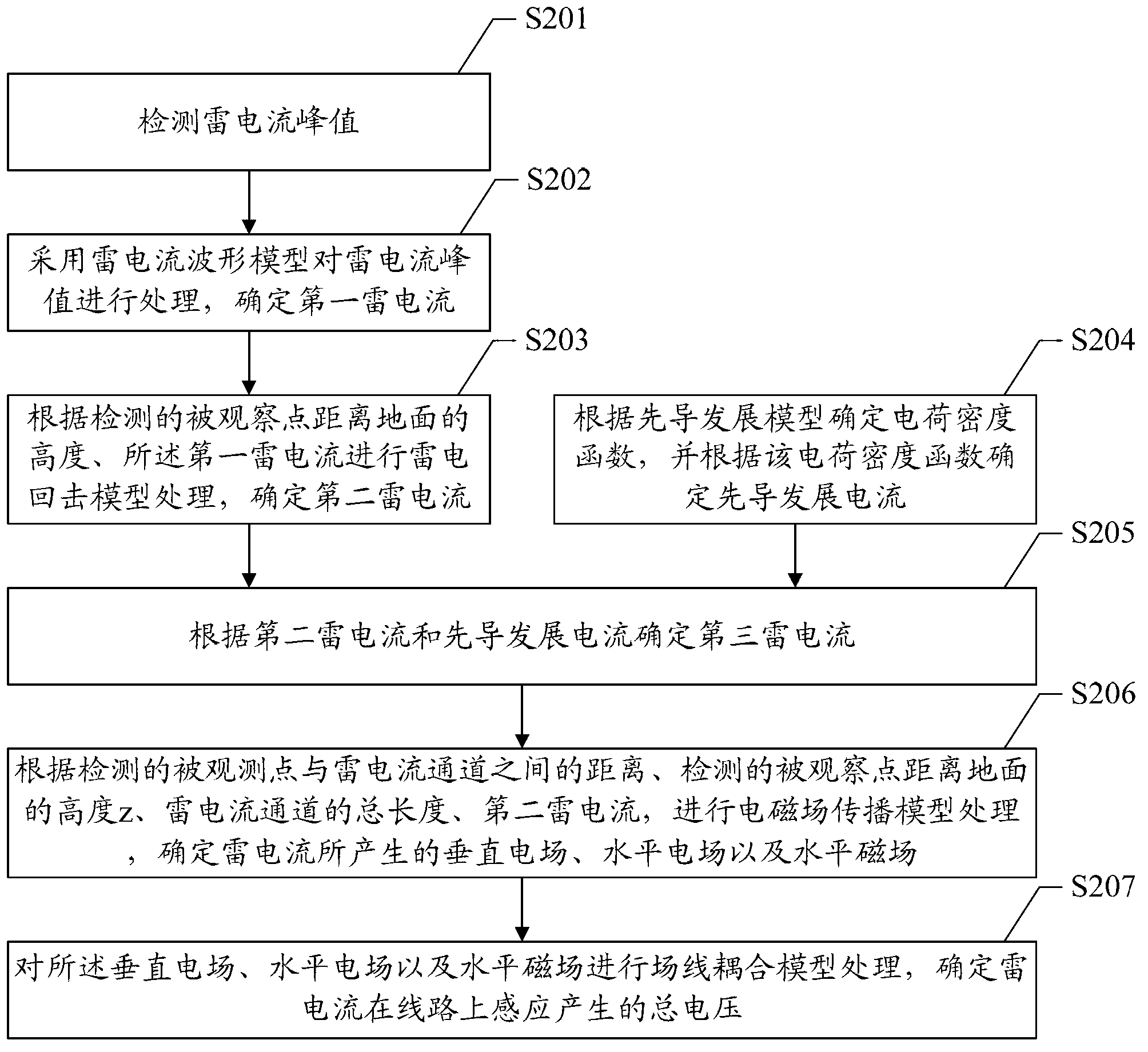
[0079] figure 2 A schematic flowchart of Embodiment 2 of the method for determining the lightning-induced voltage of a distribution line according to the present invention is shown in . exist figure 2 In the illustration, the influence of the pilot development process is considered as an example for illustration.

[0080] Such as figure 2 As shown, the method in the second embodiment includes steps:

[0081] Step S201: detecting the peak value of the lightning current;

[0082] Step S202: using the lightning current waveform model to process the lightning current peak value to determine the first lightning current i(t);

[0083] Step S203: According to the detected height z of the observed point from the ground and the first lightning current i(t), perform lightning return model processing, and determine the second lightning current i(z,t) considering lightning return;

[0084] Step S204: Determine the charge density function ρ(z, t) according to the leader development...


PUM


Abstract

The invention discloses a lightning induction voltage determining method and system on distributing lines. The method comprises the following steps of detecting a lightning current peak value; processing the lightning current peak value by adopting a lightning current waveform model to determine a first lightning current i (t); carrying out lightning return stroke model processing according to a detected height z between an observed point and the ground and the first lightning current i (t) to determine a second lightning current i (z, t); carrying out electromagnetic field propagation model processing according to a detected distance r between the observed point and a lightning current passway, the detected height z between the observed point and the ground, the total length H of the lightning current passway and the second lighting current i (z, t) to determine a horizontal electric field, a vertical electric field and a horizontal magnetic field produced by the lightning current; and carrying out field line coupling model processing on the horizontal electric field, the vertical electric field and the horizontal magnetic field to determine the total voltage produced by the induction of the lightning current on the lines. The scheme of the invention can realize the accurate analysis on induced overvoltage, and increases the analysis accuracy of the lightning induced overvoltage.

Description

technical field [0001] The invention relates to the technical field of power grids, in particular to a method for determining the lightning induced voltage of a distribution line and a system for determining the lightning induced voltage of a distribution line. Background technique [0002] In the power grid system, lightning overvoltage is an important cause of power system failure. For low-voltage distribution network systems, in many cases, lightning overvoltage is caused by lightning strikes near the line and induced on overhead lines. Therefore, it is beneficial to carry out research on lightning-induced overvoltage of distribution lines A better understanding of the phenomenon of lightning-induced overvoltage on overhead lines, the mechanism of its formation and the law of its occurrence, and then a more reasonable structural design of the overhead lines of the distribution network can be carried out, and effective protective measures can be taken to control the overvo...

Claims


Application Information

Patent Timeline
IPC IPC(8): G01R19/165
Inventor 陆国俊刘宇熊俊余占清李盛楠
Owner GUANGZHOU POWER SUPPLY CO LTD
Why Eureka
Try Eureka