Dynamic grating for 2D-to-3D (two-dimension to three-dimension) conversion

A dynamic grating and 3D technology, applied in optics, optical components, nonlinear optics, etc., can solve problems such as narrow working temperature range of liquid crystal molecules, narrow viewing angle range, and complex devices

Inactive Publication Date: 2013-08-14
FUZHOU UNIV
View PDF7 Cites 19 Cited by
  • Summary
  • Abstract
  • Description
  • Claims
  • Application Information

AI Technical Summary

Problems solved by technology

This method has the following disadvantages: complex device, high cost of liquid crystal lens, narrow viewing angle range, narrow working temperature range of liquid crystal molecules, etc.

Method used


Image

  • Dynamic grating for 2D-to-3D (two-dimension to three-dimension) conversion
  • Dynamic grating for 2D-to-3D (two-dimension to three-dimension) conversion
  • Dynamic grating for 2D-to-3D (two-dimension to three-dimension) conversion

Examples


Embodiment 1

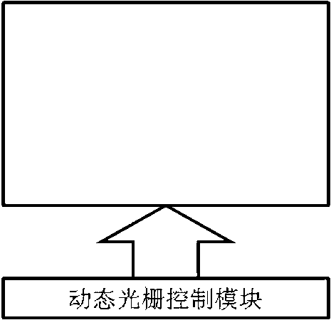
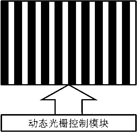
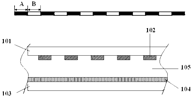
[0038] figure 1 It is an electrochromic dynamic grating that can be used for 2D / 3D conversion provided by the embodiment of the present invention. It is characterized in that it includes a first control layer, a second control layer, a grating material layer and a control module. In this embodiment, The grating material layer is an electrochromic material layer.

[0039] The first control layer includes: a first transparent substrate 101, a first transparent electrode 102; in this embodiment, the first transparent electrodes can be strip-shaped, sawtooth-shaped or stepped, and the first transparent electrodes are spaced from each other and parallel to the lower surface of the first transparent substrate. The second control layer includes: a second transparent substrate 103 and a second transparent electrode 104; the second transparent electrode is a surface electrode and is arranged on the upper surface of the second transparent substrate. The electrochromic grating material...

Embodiment 2

[0046] Figure 4 It is a thermochromic dynamic grating that can be used for 2D / 3D conversion provided by the embodiment of the present invention. It is characterized in that it includes a first control layer, a second control layer, a grating material layer and a control module. In this embodiment, The grating material layer is a thermochromic material layer.

[0047] The first control layer includes: a first transparent substrate 201, and a first transparent electrode 202; the first transparent electrodes can be in the shape of strips, zigzags and steps, and are spaced from each other and arranged in parallel on the first transparent substrate lower surface. The second control layer includes: a second transparent substrate 203 and a second transparent electrode 204; the second transparent electrode is a surface electrode and is arranged on the upper surface of the second transparent substrate. The thermochromic grating material layer 205 is placed between the first control ...

Embodiment 3

[0053] Figure 5 It is a piezochromic dynamic grating and its control method that can be used for 2D / 3D conversion provided by the embodiment of the present invention. It is characterized in that it includes a first control layer, a second control layer, a grating material layer and a control module; In an embodiment, the grating material layer is a piezochromic material layer.

[0054] The first control layer includes: a first transparent substrate 301, and a first transparent electrode 302; the first transparent electrodes can be in the shape of strips, zigzags and steps, and are spaced from each other and arranged in parallel on the first transparent substrate lower surface. The second control layer includes: a second transparent substrate 303 and a second transparent electrode 304; the second transparent electrode is a surface electrode and is arranged on the upper surface of the second transparent substrate. The piezochromic grating material layer 305 is placed between ...


PUM


Abstract

The invention discloses a dynamic grating for 2D-to-3D (two-dimension to three-dimension) conversion and a control method of the dynamic grating. The dynamic grating comprises a first control layer, a second control layer, a grating material and a control module. The first control layer comprises a first transparent substrate and a first transparent electrode. The second control layer comprises a second transparent substrate and a second transparent electrode. The second transparent electrode is a planar electrode and is arranged on the upper surface of the second transparent substrate. The grating material is arranged between the first control layer and the second control layer. The control module controls voltage between the first transparent electrode and the second transparent electrode and is used for adjusting the dynamic grating to be in a transparent state to realize a 2D display effect or adjusting the dynamic grating to have a nontransparent area and become a light and shade alternate grating to realize a 3D display effect. The dynamic grating for 2D-to-3D conversion has the advantages that the structure is simple, the cost is low, the 2D display and the 3D display can be simultaneously realized in different areas on a screen, the conversion switching between 2D and 3D is easy to realize and the using effect of display devices is improved.

Description

technical field [0001] The invention relates to the field of stereoscopic display, in particular to a dynamic grating for 2D / 3D conversion. Background technique [0002] Due to the development of display technology, 3D technology will become the mainstream of future display, and 3D stereoscopic display technology can be mainly divided into glasses-wearing and naked-eye types. Glasses-wearing 3D display can be realized through active shutter glasses and passive polarized glasses; naked-eye 3D display can be divided into parallax-shielding grating, lenticular lens and directional backlight. At present, 3D image resources are relatively scarce. If the mutual conversion between 2D and 3D modes can be realized according to the format of the displayed image, the use efficiency of the display device can be improved. Compared with a stereoscopic display device with only a single stereoscopic display function, a 2D / 3D switchable stereoscopic display device can allow users to freely ...

Claims


Application Information

Patent Timeline
Patent Type & Authority Applications(China)
IPC IPC(8): G02F1/15G02F1/155G02B27/22
Inventor 叶芸郭太良张永爱林志贤周雄图林金堂颜敏刘玉会曾祥耀陈填源
Owner FUZHOU UNIV
Why Eureka
Try Eureka