Light emitting module and lighting device for vehicle

a technology of light emitting modules and lighting devices, which is applied in the direction of lighting support devices, instruments, and semiconductor/solid-state device details, etc., can solve the problems of increasing the possibility of short circuits, and achieve the effects of preventing short circuits, convenient design, and convenient operation

Active Publication Date: 2008-01-10
KOITO MFG CO LTD +1
View PDF8 Cites 55 Cited by
  • Summary
  • Abstract
  • Description
  • Claims
  • Application Information

AI Technical Summary

Benefits of technology

[0010]Therefore, a light emitting module and a lighting device for a vehicle according to one or more embodiments of the invention prevent the generation of a short circuit.
[0015]In the positioning and fixing state to the radiating member, accordingly, it is possible to prevent the generation of a short circuit without causing the planar electrode portion to come in contact with the radiating member.
[0016]According to a second aspect of embodiments of the invention, the pair of planar electrode portions are formed in the outer peripheral portion positioned on an opposite side with the semiconductor light emitting device interposed therebetween. Therefore, a design can easily be carried out for a position in which the feeding terminal of the feeding attachment is formed. Consequently, it is possible to facilitate the design.
[0017]According to a third aspect of embodiments of the invention, a part of the pair of planar electrode portions are covered with an insulating layer to form a non-exposure region, which is not exposed to the device disposing surface of the ceramic board. Therefore, it is possible to easily form the exposure region and the non-exposure region.
[0019]In the positioning and fixing state to the radiating member, accordingly, it is possible to prevent the generation of a short circuit without causing the planar electrode portion to come in contact with the radiating member.

Problems solved by technology

For this reason, there is an increased possibility that a short circuit might be caused.

Method used


Image

  • Light emitting module and lighting device for vehicle
  • Light emitting module and lighting device for vehicle
  • Light emitting module and lighting device for vehicle

Examples


Embodiment Construction

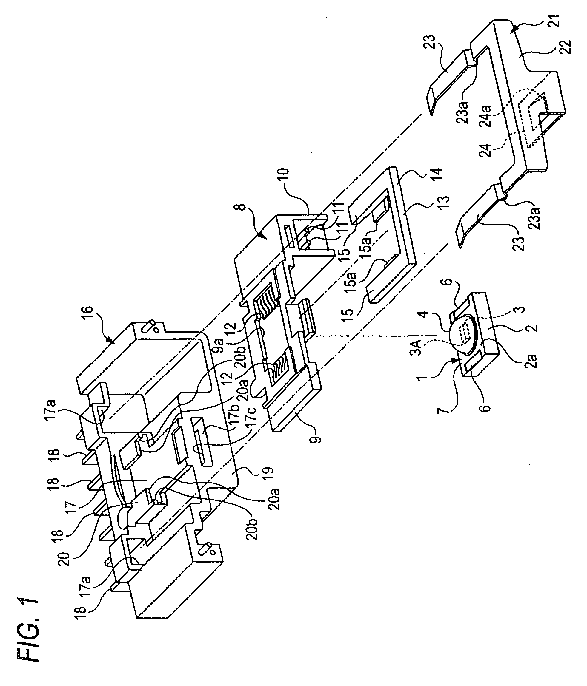
[0030]Embodiments of a light emitting module and a lighting device for a vehicle according to the invention will be described below with reference to the accompanying drawings.

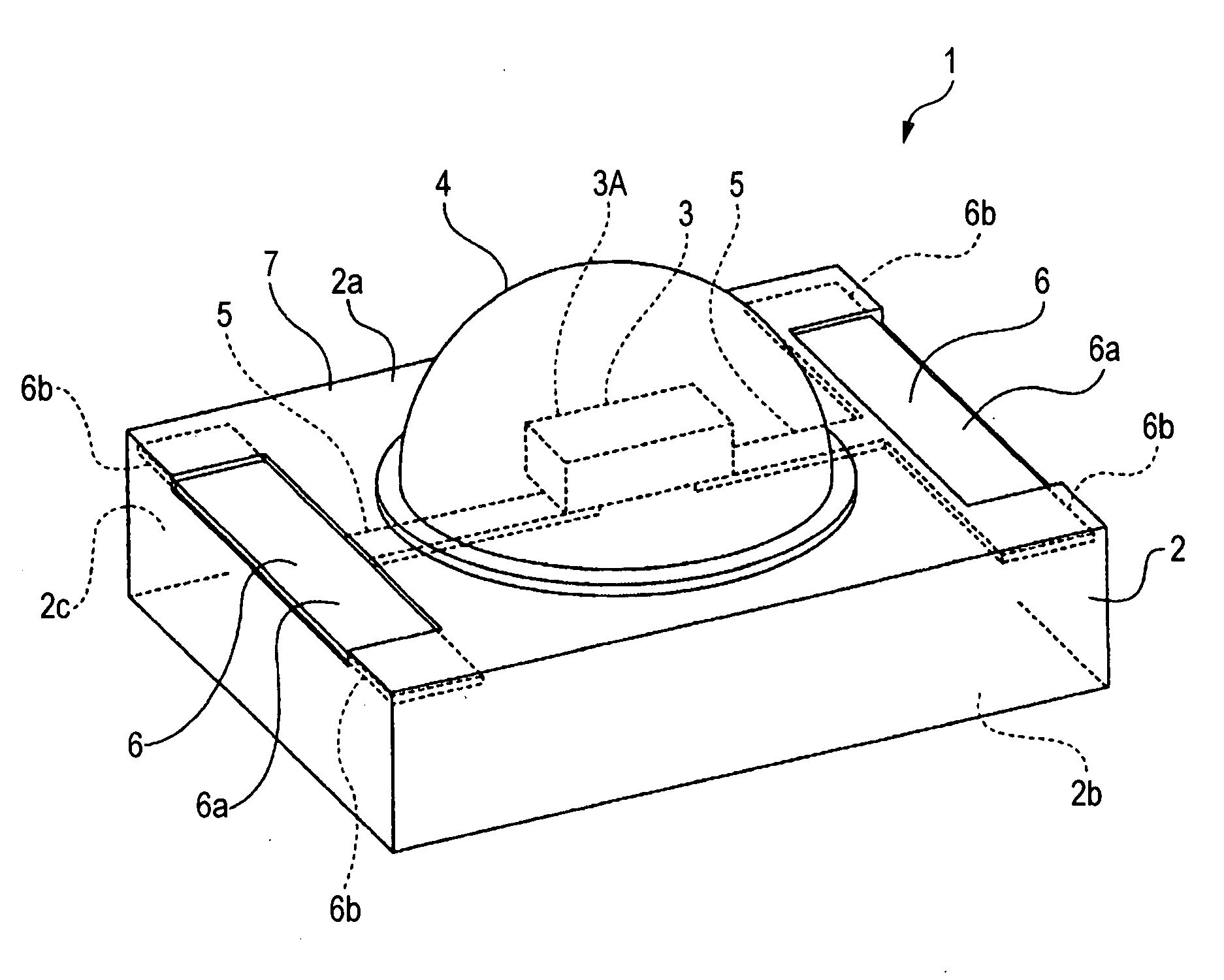
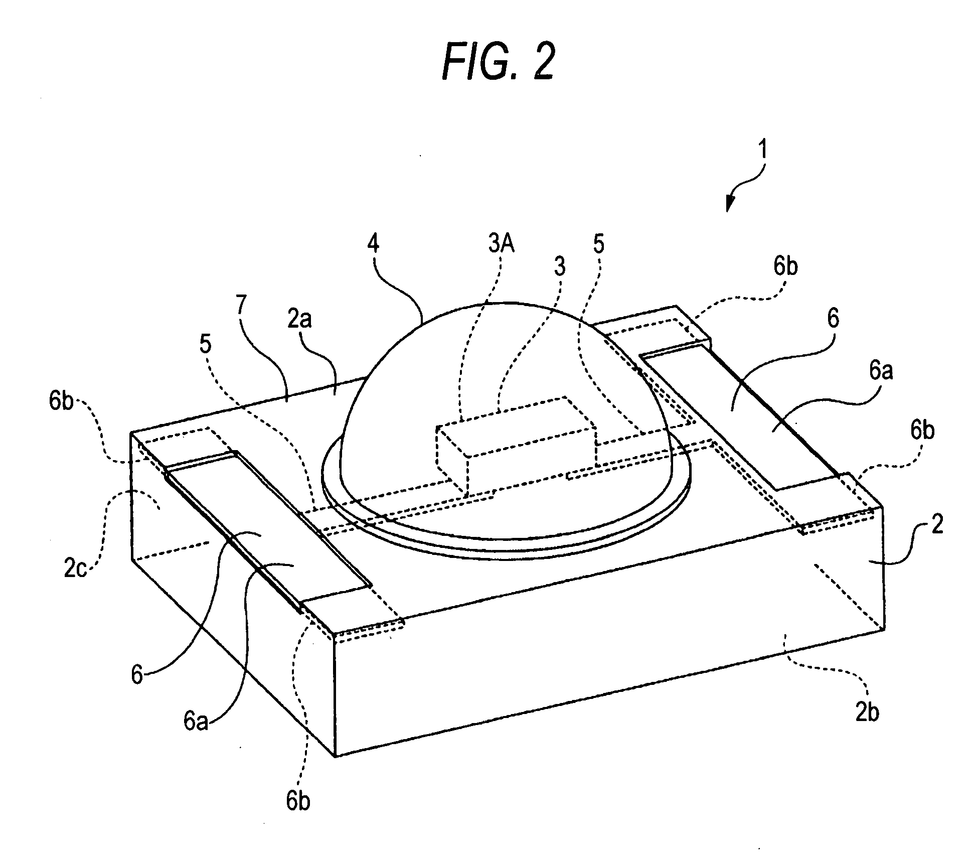
[0031]A light emitting module 1 comprises a ceramic board 2, a semiconductor light emitting device 3 such as an LED (light emitting diode) chip, and a cover 4 (see FIG. 1).

[0032]The ceramic board 2 is formed in a rectangular shape, for example, a shape of an oblong rectangle. For the ceramic board 2, various boards such as an aluminum nitride ceramic board, an alumina ceramic board, a mullite ceramic board, and a glass ceramic board are used.

[0033]Two directions, which are orthogonal to each other in a vertical direction and along which respective side edges are extended, are set to be a first direction (a long direction) and a second direction (a short direction) in the ceramic board 2 (see FIG. 2). One of the surfaces (an upper surface) in the vertical direction is formed as a device disposing surface 2a on ...


PUM


Abstract

A ceramic board is formed in an almost rectangular shape and has one side surface of an outer peripheral surface formed as an abutting surface, which is caused to abut on positioning surfaces of a radiating member, and one surface in a vertical direction formed as a device disposing surface on which a semiconductor light emitting device is to be disposed. Predetermined conductive patterns are formed on the ceramic board. A light emitting portion has a semiconductor light emitting device. A pair of positive and negative planar electrode portions are formed on the ceramic board and connected to the semiconductor light emitting device through the conductive patterns. At least a part of the pair of planar electrode portions are set to be exposure regions exposed to the device disposing surface of the ceramic board and the exposure regions are positioned in portions other than a portion linked to the abutting surface in an outer peripheral portion of the device disposing surface.

Description

BACKGROUND OF INVENTION[0001]1. Field of the Invention[0002]The present invention relates to a light emitting module and a lighting device for a vehicle, and more particularly to the forming of exposure regions of a pair of planar electrode portions in predetermined positions of a ceramic board.[0003]2. Background Art[0004]Some light emitting modules use a semiconductor light emitting device such as a light emitting diode (LED) as a light source. By way of example, the light emitting module is provided in a lighting device for a vehicle which irradiates, as an illuminating light, a light emitted from the light source by means of a projection lens (for example, see Patent Document 1).[0005]In the light emitting module described in the Patent Document 1, one side surface of outer peripheral surfaces of a radiating board is fixed to a radiating member formed by a metal material having a high thermal conductivity (a light source pedestal 50a in the Patent Document 1) in an abutting stat...

Claims


Application Information

Patent Timeline
Patent Type & Authority Applications(United States)
IPC IPC(8): G02B6/36F21S8/10F21V29/00F21W101/10F21W107/10F21Y101/02
CPCF21K9/00F21S48/1109F21S48/1159F21Y2101/02H01L33/486H01L2924/0002H01L33/62F21V19/0015H01L2924/00F21Y2115/10F21S41/148F21S41/192B60Q1/00F21V29/00
Inventor TAKEDA, HITOSHITOKIDA, TSUKASAWATANABE, KAZUNORIONO, MASATO
Owner KOITO MFG CO LTD
Why Eureka
Try Eureka