

Corona discharge ionization sources for mass spectrometric and ion mobility spectrometric analysis of gas-phase chemical species
- Summary
- Abstract
- Description
- Claims
- Application Information
AI Technical Summary
Benefits of technology
Problems solved by technology
Method used
Image

Examples
Embodiment Construction
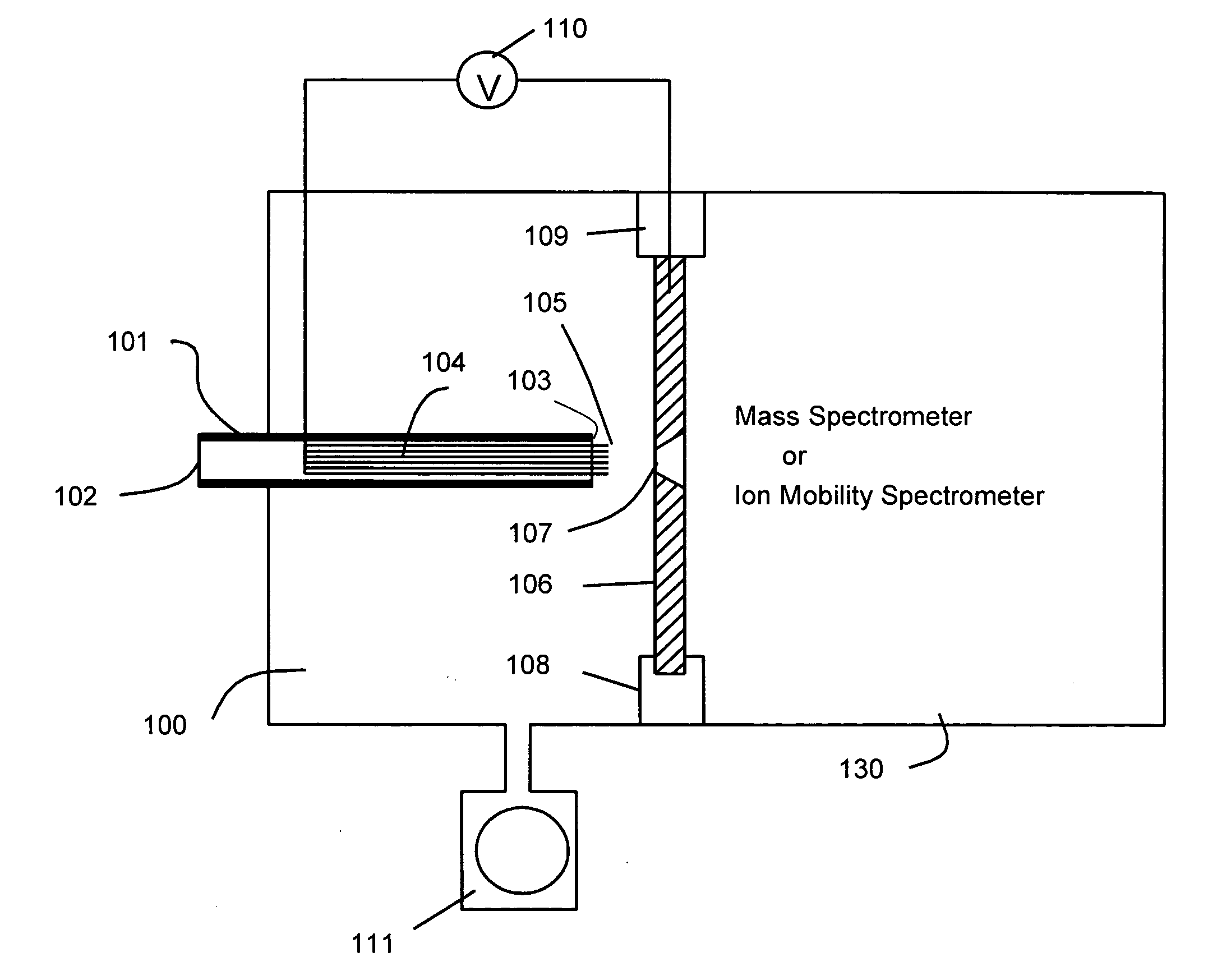
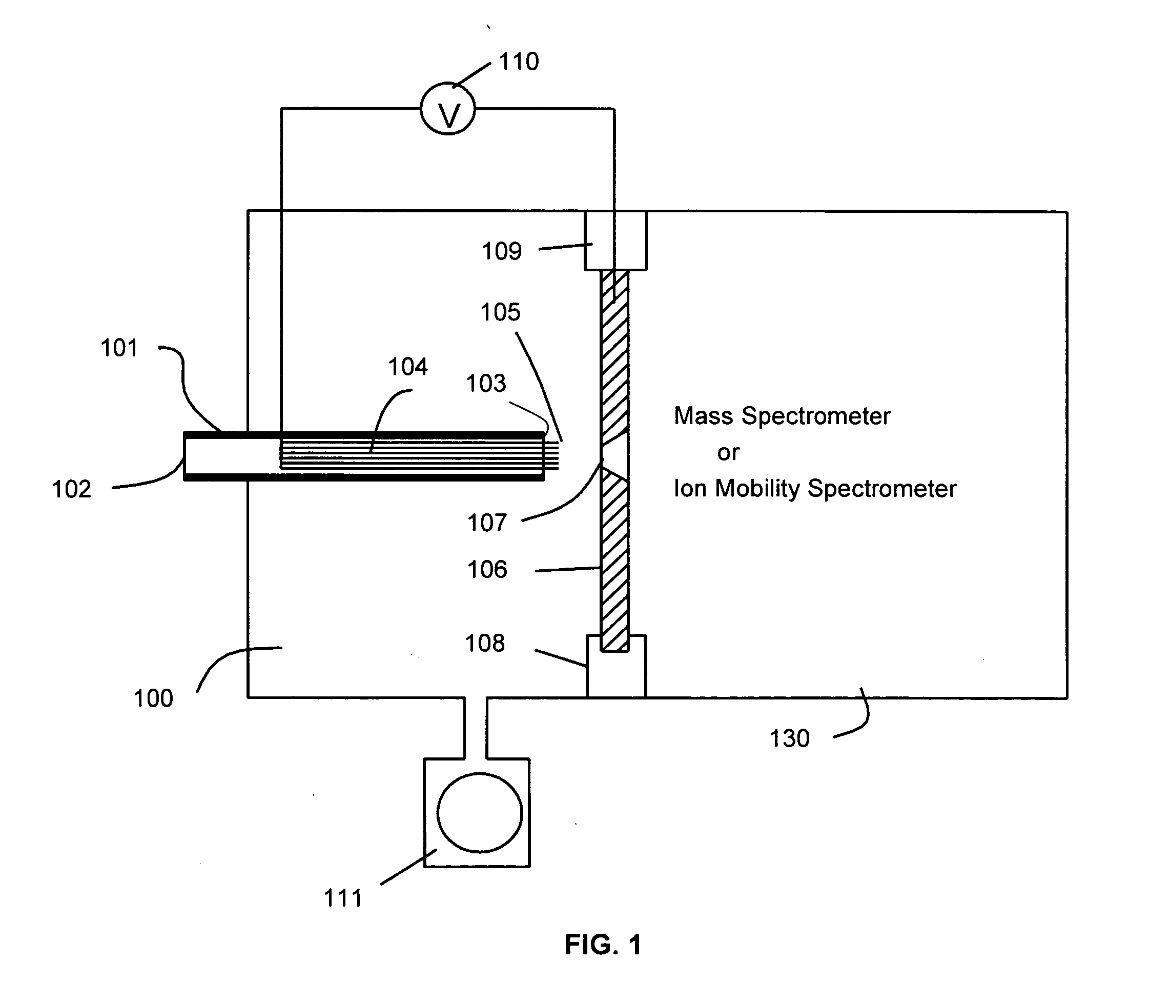
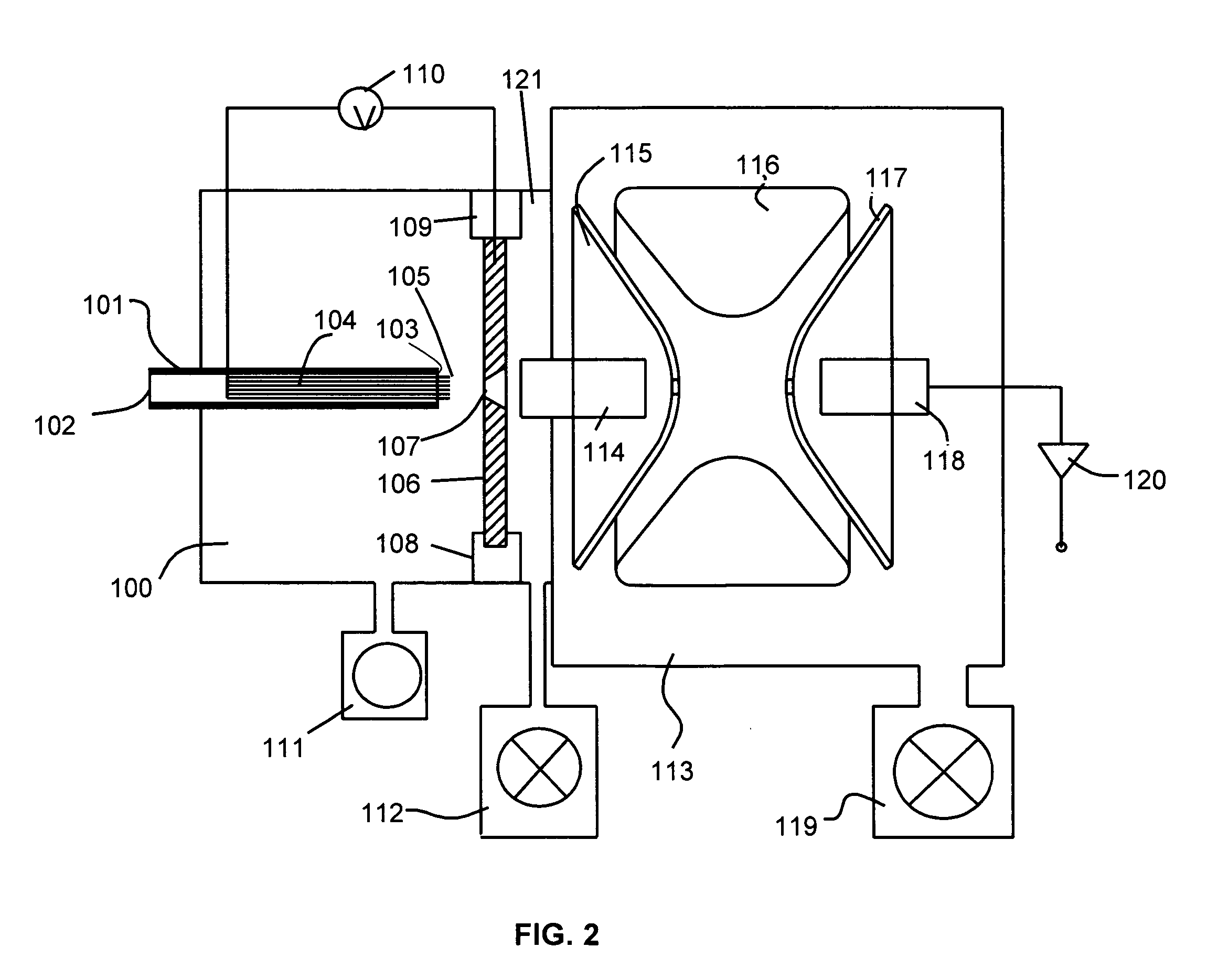
[0030] Corona discharge ionization sources with stable, reliable and robust operational characteristics are provided. The corona discharge ionization sources utilize a discharge electrode having a multi-threaded structure. This multi-threaded discharge electrode is used in a point-to plane geometry in conjunction with a plane geometry. The multi-threaded electrodes are superior to conventional needlepoint electrodes in which a single defect in the electrode needlepoint can lead to failure or serious degradation of the corona discharge.
[0031] An exemplary discharge electrode, in accordance with the principles of the present invention, is configured with multiple discharge point tips. In this configuration failure of one or a even few tips does not degrade the corona discharge as the other tips in the electrode provide redundancy in operation.
[0032] In an electrode, the multiple discharge tips or points are disposed at the end a multiple thread structure or bundle for the discharge ...
PUM
 Abstract
Description
Claims
Application Information