
Method of and apparatus for ionizing sample gas

a sample gas and ionization technology, applied in the field of ionizing a sample gas, can solve the problems of reducing ionization efficiency, and achieve the effect of raising ionization efficiency in penning ionization

Active Publication Date: 2006-08-15
UNIVERSITY OF YAMANASHI
View PDF2 Cites 17 Cited by
  • Summary
  • Abstract
  • Description
  • Claims
  • Application Information

AI Technical Summary

Benefits of technology

"The present invention provides a method and apparatus for ionizing a sample gas using a rare gas and a positive voltage. This method results in higher ionization efficiency and prevents recombination of ions and electrons. The apparatus includes an ionization space with a miniscule hole for introducing ionized gas to a mass analyzer, a discharge electrode and an electron-capture electrode, and a rare gas introduction system. The method involves introducing a rare gas into the ionization space, exciting the rare gas with a positive voltage to produce a metastable excited species, inducing Penning ionization by introducing a sample gas into the space and capturing electrons released from the gas using the electron-capture electrode. The positive ionized gas is then guided to a mass analyzer through the miniscule hole. The method and apparatus provide a reliable and efficient tool for ionizing sample gases for mass analysis."

Problems solved by technology

If these electrons recombine with positive ions, however, ionization efficiency declines.

Method used


Image

  • Method of and apparatus for ionizing sample gas
  • Method of and apparatus for ionizing sample gas
  • Method of and apparatus for ionizing sample gas

Examples


first embodiment

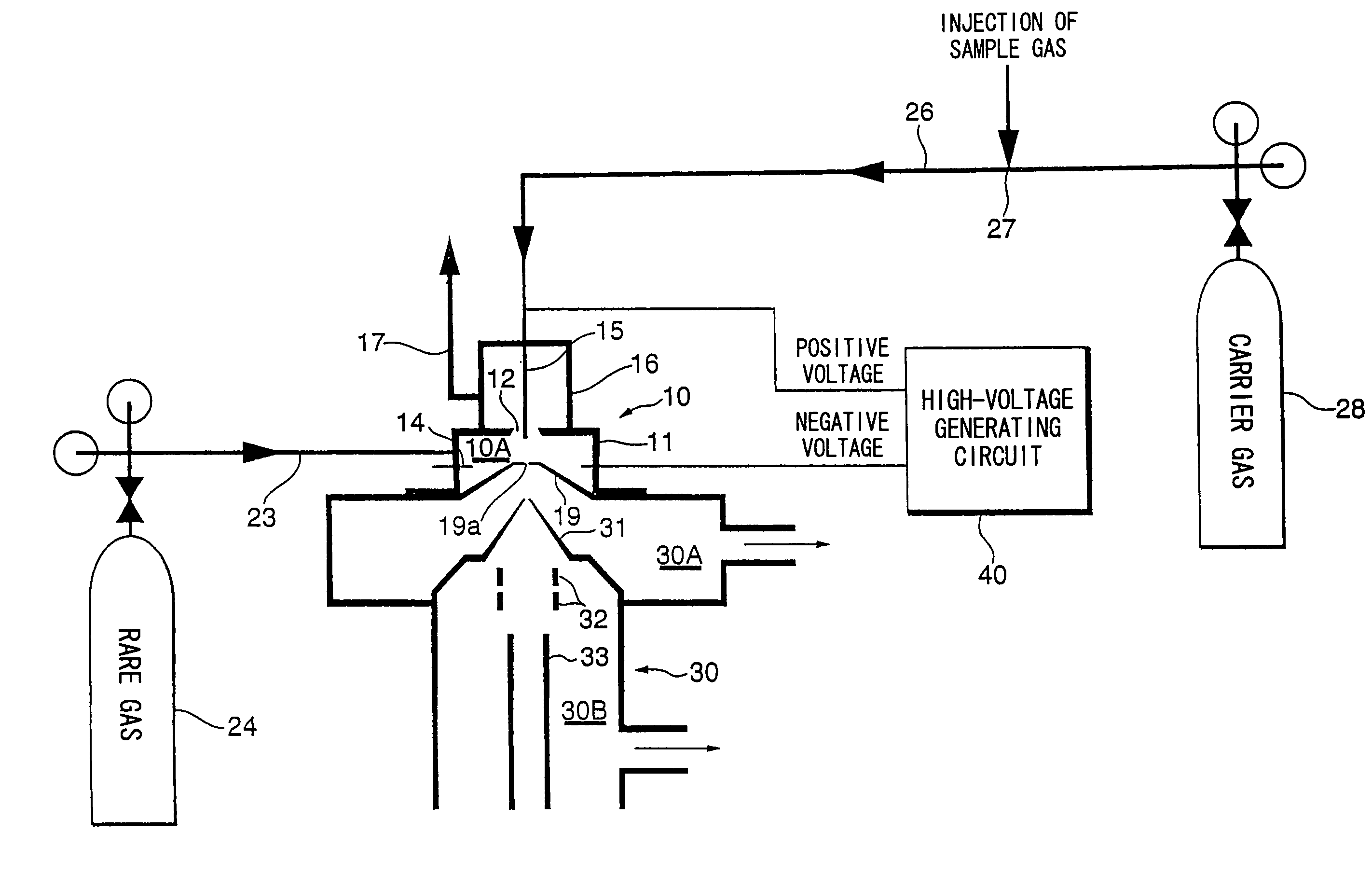
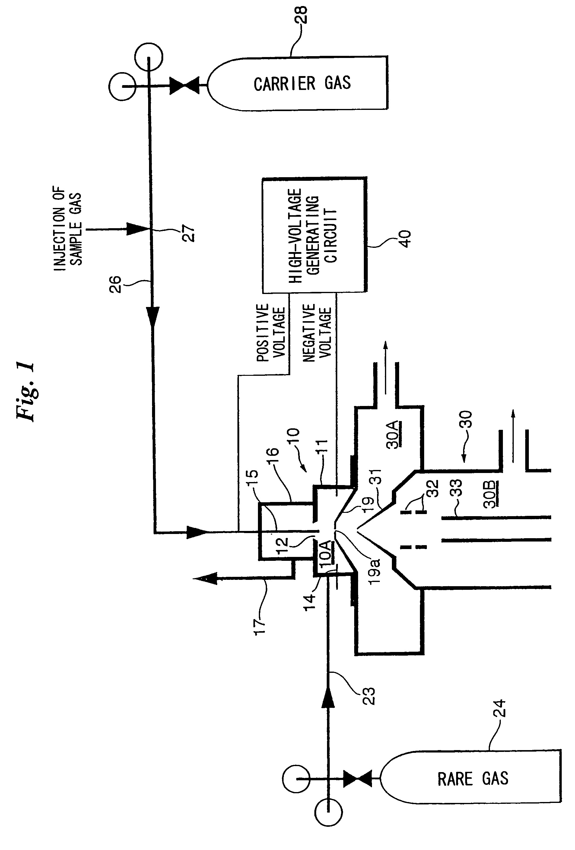
[0042]FIG. 1 illustrates the overall configuration of a system for analyzing a sample gas.

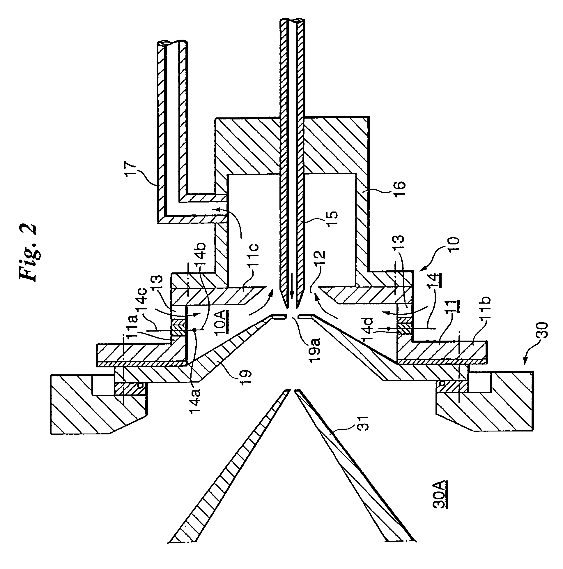
[0043]An ionization apparatus 10 is mounted on a mass analyzer (a quadrupole mass spectrometer in this embodiment) 30. More specifically, an ionization space 10A is formed by an orifice 19, which is secured to the mass analyzer 30 and provided at its center with a miniscule hole 19a for introducing ions into the mass analyzer 30, and a diaphragm 11 secured to the mass analyzer 30 and having a substantially circular cylindrical recess. The orifice 19 and diaphragm 11 are both made of an electrical conductor (metal).

[0044]A rare gas at approximately atmospheric pressure is introduced into the ionization space 10A at a plurality of locations at the periphery thereof from a rare gas cylinder 24 through a rare gas supply tube (which is flexible) 23. A corona-discharge electrode 14 is provided inside the ionization space 10A at the periphery thereof in the vicinity of rare gas introduction ports of t...

second embodiment

[0064]FIG. 7 illustrates an ionization apparatus according to a second embodiment of the present invention. This ionization apparatus differs from that shown in FIG. 2 only in that the corona-discharge electrode 14 is not provided; other structural aspects are the same as those of the ionization apparatus shown in FIG. 2. Accordingly, components identical with those shown in FIG. 2 are designated by like reference characters and need not be described again.

[0065]The ionization apparatus of the second embodiment produces negative ions. Accordingly, the ionization apparatus illustrated in FIG. 7 is used (operated) in a manner different from that of the ionization apparatus shown in FIG. 2.

[0066]A carrier gas such as a rare gas or oxygen is introduced into the ionization space 10A from the introduction ports 13 and produces a flow, and a negative high voltage (e.g., −500 to −3000V) is applied to the sample gas introduction capillary 15 to produce a corona discharge at the tip of the ca...


PUM

PropertyMeasurementUnit
voltageaaaaaaaaaa
positive voltageaaaaaaaaaa
metastable energyaaaaaaaaaa

Abstract

Ionization efficiency is improved in Penning ionization capable of selective ionization. A metastable excited species of a rare gas is produced by introducing the rare gas into an ionization space and inducing an electrical discharge, a sample gas is introduced into the ionization space and Penning ionization is produced owing to collision between the sample gas and the metastable excited species of the rare gas. Electrons released from atoms or molecules positively ionized by Penning ionization are captured by applying a positive potential to an electron-capture electrode placed in the ionization space, and the atoms or molecules positively ionized are guided to a mass analyzer.

Description

BACKGROUND OF THE INVENTION[0001]1. Field of the Invention[0002]This invention relates to a method of ionizing a sample gas, a method of controlling ionization and an ionization apparatus.[0003]2. Description of the Related Art[0004]Though a mass analyzing apparatus (mass analyzing method) is effective for the purpose of analyzing a sample gas, ionization of the sample gas is necessary in order to use this apparatus (method). A typical atmospheric ionization method in wide use at the present time is the APCI (Atmospheric Pressure Chemical Ionization) method, which utilizes corona discharge. This method brings about chemical ionization under atmospheric pressure by spraying a sample solution and simultaneously heating the same to vaporize the solvent, placing a needle-shaped high-voltage electrode in the vaporized solvent and applying a positive or negative high voltage to the electrode to thereby induce corona discharge. With APCI, first the carrier gas that is the main component is...

Claims


Application Information

Patent Timeline
Patent Type & Authority Patents(United States)
IPC IPC(8): G01N21/01G01N21/51G01N23/10G01N23/12G01N27/68G01N27/62H01J49/10H01J49/14H01J49/26
CPCH01J49/145
Inventor HIRAOKA, KENZO
Owner UNIVERSITY OF YAMANASHI
Learn More