
Atmospheric pressure plasma assembly

a technology of atmospheric pressure and plasma, which is applied in the direction of prosthesis, liquid/gas/vapor textile treatment, and textile treatment by spraying/projecting. it can solve the problems of non-polar surface, poor disposition to coating or gluing, and inability to achieve processes which are impossible or difficul

Inactive Publication Date: 2005-08-18
DOW CORNING IRELAND
View PDF43 Cites 59 Cited by
  • Summary
  • Abstract
  • Description
  • Claims
  • Application Information

AI Technical Summary

Benefits of technology

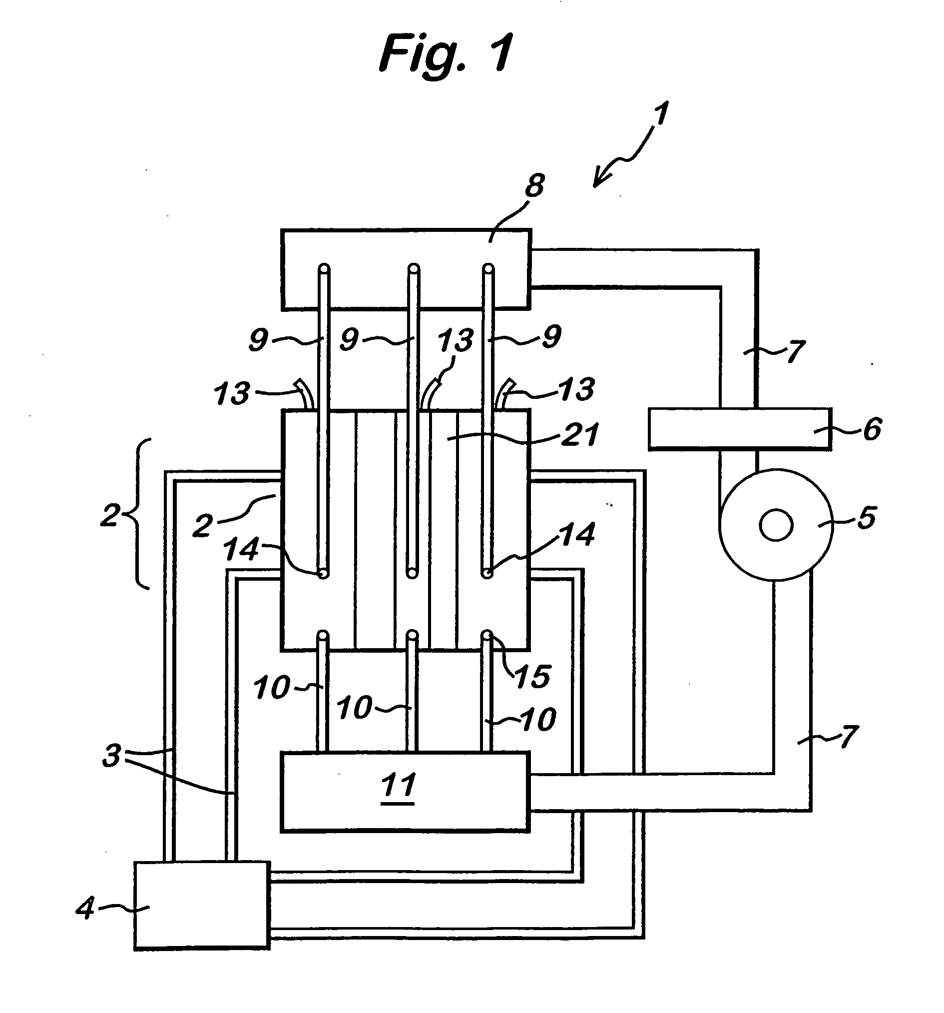
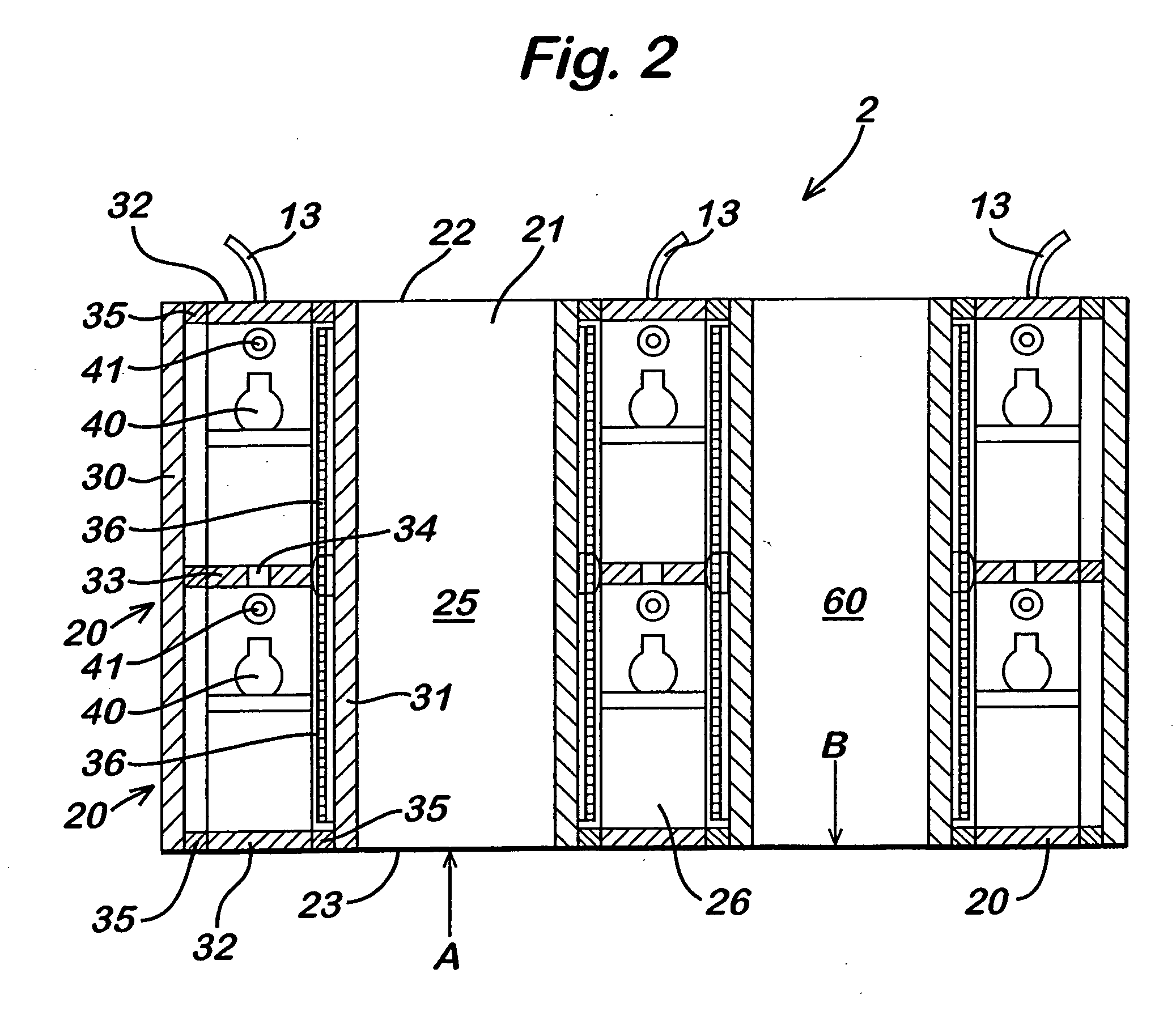
[0029] Ideally the cooling liquid covers the face of the electrode remote from the dielectric plate. The cooling conductive liquid is preferably water and may contain conductivity controlling compounds such as metal salts or soluble organic additives. Ideally, the electrode is a metal electrode in contact with the dielectric plate. In one embodiment, there is a pair of metal electrodes each in contact with a dielectric plate. The water in accordance with the present invention acts as well as being an extremely efficient cooling agent to also assist in providing an efficient electrode.
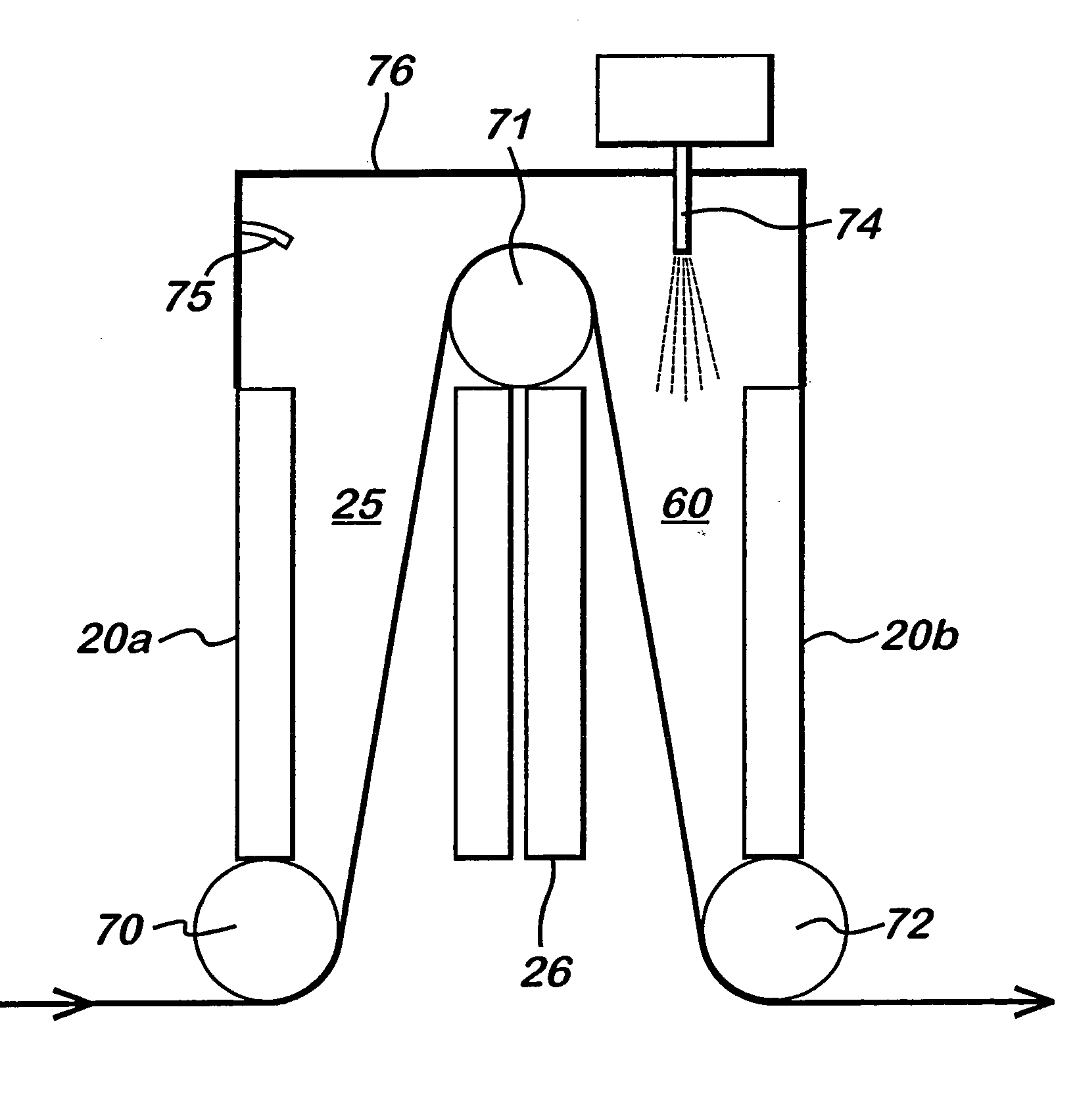
[0037] Any appropriate combination of plasma treatments may be used, for example the first plasma region may be utilised to clean the surface of the substrate by plasma treating using a helium gas plasma and the second plasma region is utilised to apply a coating, for example, by application of a liquid or solid spray through an atomiser or nebuliser as described in the applicants co-pending application WO 02 / 28548, which was published after the priority date of this application. The application of a coating of a liquid spray is particularly suited as the droplets in the spray will be subjected to gravitational feed unlike a gas such that the nebuliser is positioned in the assembly such that gravity feed of the coating material results in the coating precursor only passing through the second plasma region, thereby relying on gravity to prevent transfer of coating precursor into the first plasma region.
[0047] Substrates coated by the method of the present invention may have various uses. For example, a silica-based coating, generated in an oxidising atmosphere, may enhance the barrier and / or diffusion properties of the substrate, and may enhance the ability of additional materials to adhere to the substrate surface. A halo-functional organic or siloxane coating (e.g. perfluoroalkenes) may increase hydrophobicity, oleophobicity, fuel and soil resistance, enhance gas and liquid filtration properties and / or the release properties of the substrate. A polydimethylsiloxane coating may enhance water resistance and release properties of the substrate, and may enhance the softness of fabrics to touch; a polyacrylic acid polymeric coating may be used as a water wettable coating, bio-compatible coating or an adhesive layer to promote adhesion to substrate surface or as part of laminated structure. The inclusion of colloidal metal species in the coatings may provide surface conductivity to the substrate, or enhance its optical properties. Polythiophene and polypyrrole give electrically conductive polymeric coatings which may also provide corrosion resistance on metallic substrates. Acidic or basic functionality coatings will provide surfaces with controlled pH, and controlled interaction with biologically important molecules such as amino acids and proteins.

Problems solved by technology

Furthermore, their high energy content allows them to achieve processes which are impossible or difficult through the other states of matter, such as by liquid or gas processing.
Thus, for example, polyolefins, such as polyethylene and polypropylene, which are favoured for their recylability, have a non-polar surface and consequently a poor disposition to coating or gluing.
However, adoption of plasma technology has been limited by a major constraint on most industrial plasma systems, namely, their need to operate at low pressure.
Throughput is low or moderate and the need for vacuum adds capital and running costs.
However, despite their high manufacturability, these systems have failed to penetrate the market or be taken up by industry to anything like the same extent as the lower pressure, bath-processing-only plasma type.
The reason is that corona / flame systems have significant limitations.
The treatment is often non-uniform and the corona process is incompatible with thick webs or 3D workpieces while the flame process is incompatible with heat sensitive substrates.

Method used


Image

  • Atmospheric pressure plasma assembly
  • Atmospheric pressure plasma assembly
  • Atmospheric pressure plasma assembly

Examples


example

Multilayer Coating on Polypropylene Film

[0065] As an example of the potential utility of the present invention there is provided the following example in which a 25 μm thick polypropylene film was coated twice using the apparatus in accordance with the present invention. The first coating was a hydrophilic polyacrylic acid coating, the second coating being an oleophobic and hydrophobic fluoropolymer coating. A KSV CAM200 Optical Contact Angle Meter was used to characterise [0066] i) The untreated film which is hydrophobic but not oleophobic [0067] ii) the acrylic acid treated film (i) and [0068] iii) the fluoropolymer treated film (ii)

by sessile drop contact angle.

[0069] The untreated polypropylene film is hydrophobic but not oleophobic, as shown in Table 1. Note: The water contact angle indicates that this film is corona treated on receipt.

TABLE 1Contact Angle analysis of polypropylene film. (the term wets out isused to mean that no droplet formation is seen).Probe LiquidΘ (l...


PUM

PropertyMeasurementUnit
temperatureaaaaaaaaaa
pressureaaaaaaaaaa
drop sizeaaaaaaaaaa

Abstract

An atmospheric pressure plasma assembly (1) comprising a first and second pair of vertically arrayed, parallel spaced-apart planar electrodes (36) with at least one dielectric plate (31) between said first pair, adjacent one electrode and at least one dielectric plate (31) between said second pair adjacent one electrode, the spacing between the dielectric plate and the other dielectric plate or electrode of each of the first and second pairs of electrodes forming a first and second plasma regions (25,60) characterised in that the assembly further comprises a means of transporting a substrate (70,71,72) successively through said first and second plasma regions (25,60) and an atomiser (74) adapted to introduce an atomised liquid or solid coating making material into one of said first or second plasma regions.

Description

CROSS-REFERENCES TO RELATED APPLICATIONS [0001] This present application is a US national stage filing under 35 USC 371 and claims priority from PCT Application No. PCT / EP 03 / 04349 entitled “AN ATMOSPHERIC PRESSURE PLASMA ASSEMBLY” filed on Apr. 8, 2003, currently pending, which claims priority from Great Britain Patent Application 0208261.8 entitled “AN ATMOSPHERIC PRESSURE PLASMA ASSEMBLY” filed on Apr. 10, 2002, currently pending. FIELD OF INVENTION [0002] The present invention relates to an atmospheric pressure plasma assembly and a method of treating a substrate using said assembly. BACKGROUND OF THE INVENTION [0003] When matter is continually supplied with energy, its temperature increases and it typically transforms from a solid to a liquid and, then, to a gaseous state. Continuing to supply energy causes the system to undergo yet a further change of state in which neutral atoms or molecules of the gas are broken up by energetic collisions to produce negatively charged electr...

Claims


Application Information

Patent Timeline
Patent Type & Authority Applications(United States)
IPC IPC(8): A61L27/00A61L31/00D06B1/02D06B19/00D06M10/02H05H1/24
CPCH05H1/24H05H1/2406H01J37/32
Inventor GOODWIN, ANDREW JAMESLEADLEY, STUARTSWALLOW, FRANKDOBBYN, PETER
Owner DOW CORNING IRELAND
Learn More