
Pulse health instrument

a technology of pulse health and electrodes, applied in the direction of external electrodes, electrotherapy, therapy, etc., can solve the problems of poor application effect, insufficient treatment of prior art pulse health devices, and inability to provide electrodes for pulse supply under stable conditions, so as to improve the contact feeling of belt installation

Inactive Publication Date: 2003-08-14
YA MAN LTD
View PDF1 Cites 55 Cited by
  • Summary
  • Abstract
  • Description
  • Claims
  • Application Information

AI Technical Summary

Benefits of technology

[0013] In accordance with the present invention, even when the belt with the electrodes has to be applied to a projected position of the body, such as, waist, buttocks and abdomen, the slits can adapt such projections of the body. Therefore, the health device of the present invention can make intimate and stable contact of the pulse supply electrodes to such projections of the body by simple structure of the device, so that sufficient treatment effect can be expected.
[0034] Accordingly, the pulse health device of the present invention can solve the problems of direct contacts to the skin of the user, which problems are occurred by unevenness or projected edge of the planar electrode, resulting from electrode direct adhering to the belt. Then, the contact feeling when the belt is installed can be well improved.

Problems solved by technology

However, the above pulse health device with belt installation can provide merely small range of the surface of the body within which the belt can be wrapped on.
Moreover, this pulse health device can not provide the electrodes for supply of pulse under stable condition.
Therefore, the prior art pulse health device can not give the sufficient treatment on such range having many and much projections.
Therefore, the prior art pulse health device will take much time and care to start the treatment, and further, the user can not move freely nor exercise during the treatment, so that there is much limitation of the application.
Then, the electrode must have some uneven margin or projected edge on its peripheral, so that strong pulse current can be charged on such projected edge, or such uneven margin or the projected edge of the electrode can make the skin of the user contact, that may make bad feeling on the user during its installation.

Method used


Image

  • Pulse health instrument
  • Pulse health instrument
  • Pulse health instrument

Examples


first embodiment

[0051] (First Embodiment)

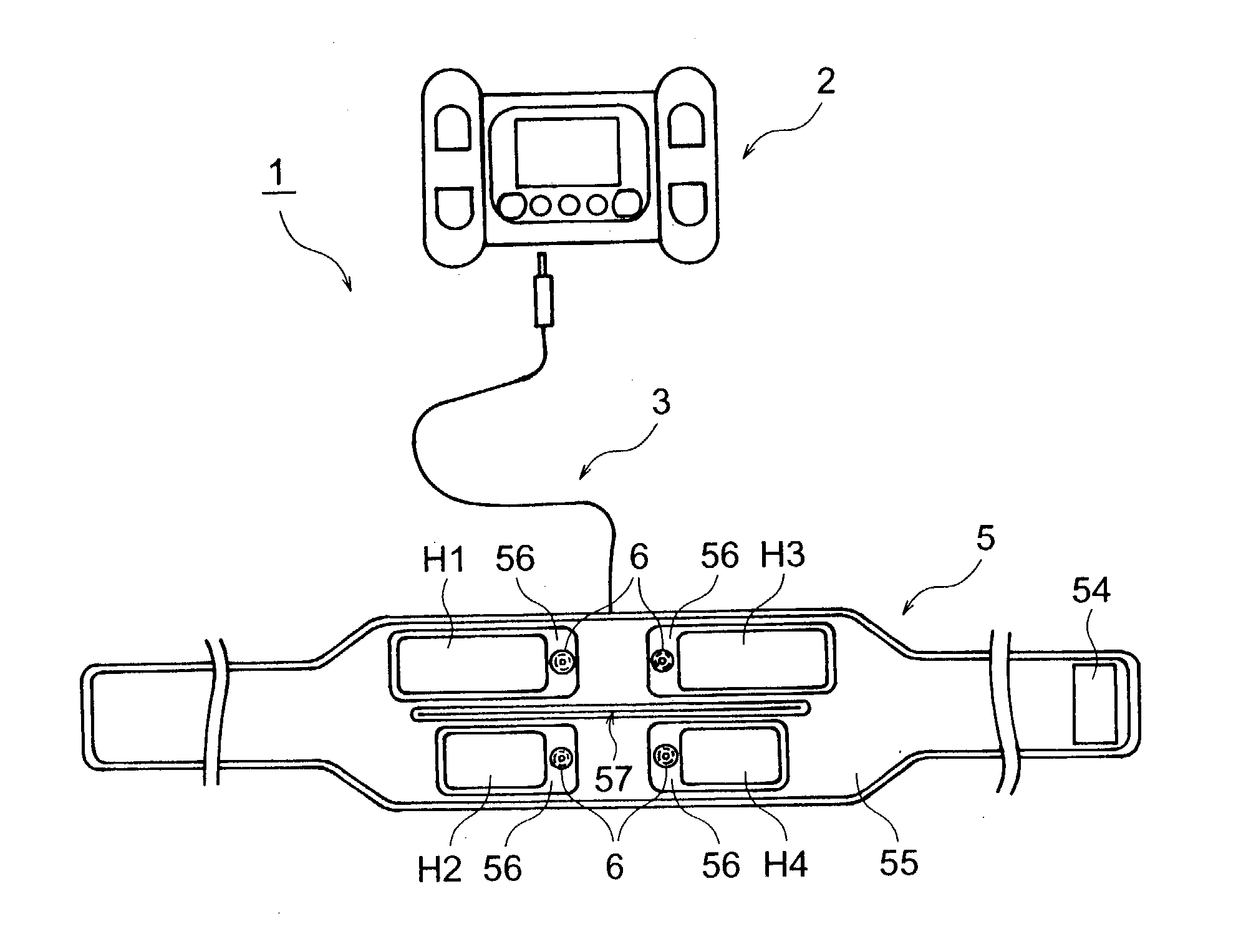
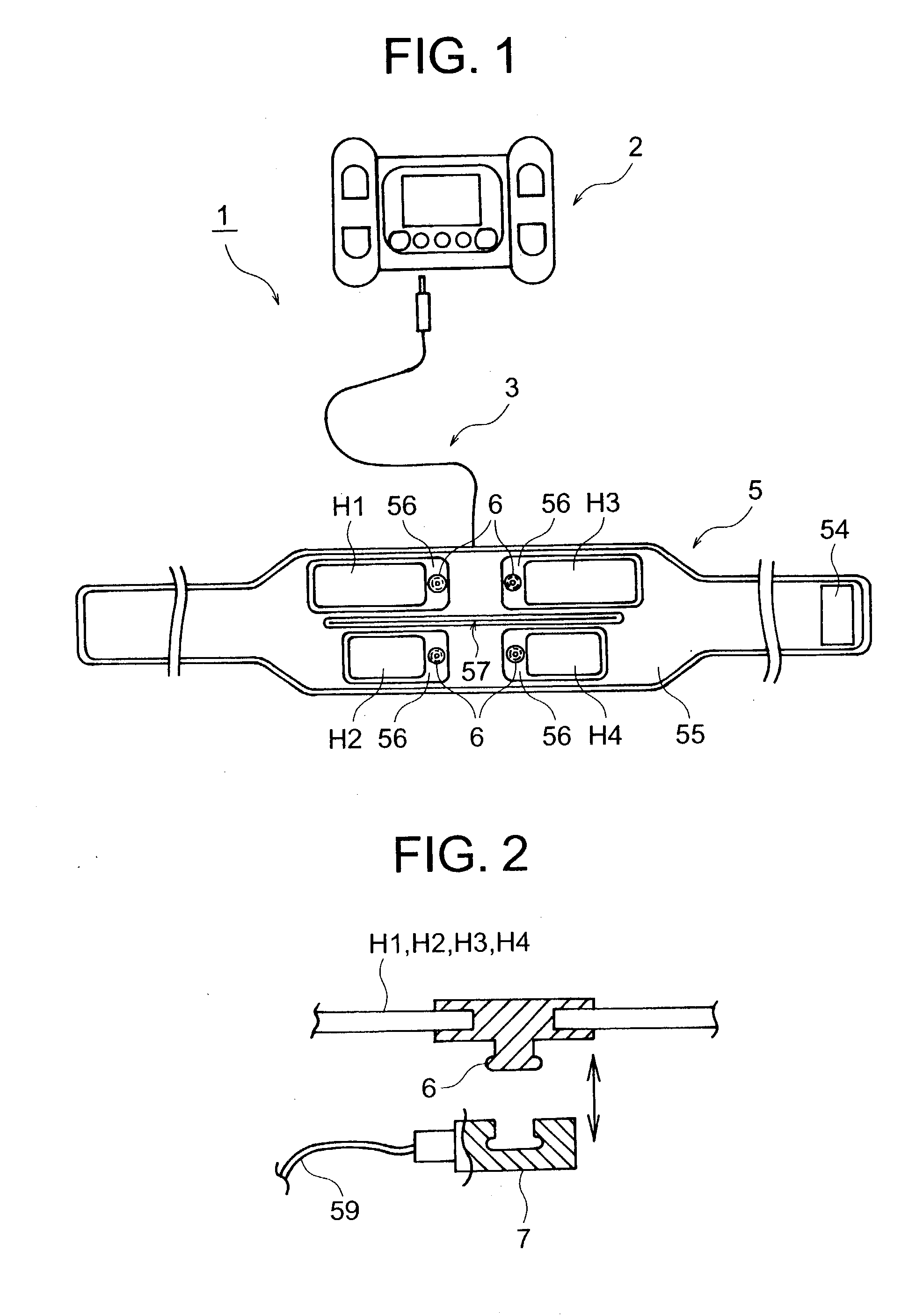
[0052] FIG. 1 shows a schematic view of whole arrangement of a pulse health device of the first embodiment of the present invention.

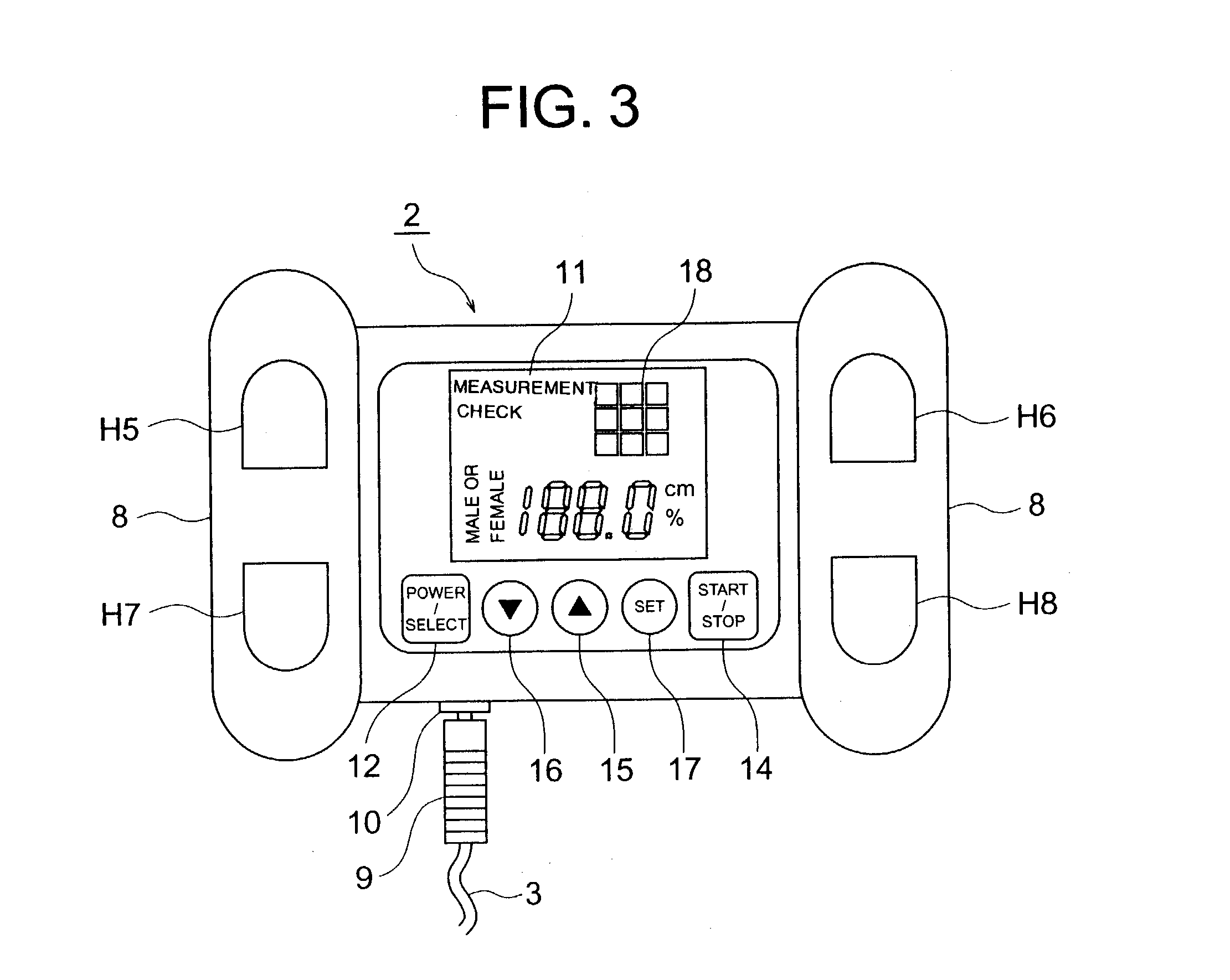
[0053] As shown in the drawings, this pulse health device 1 can treat to shape up the body of the user by applying pulse current to the body. The pulse health device 1 comprises a portable control unit 2, and an electrode belt 2 the electrodes of which are connected to the control unit 2 through a cable 3.

[0054] An electrode belt 5 has four planar electrodes H1, H2, H3 and H4. Those planar electrodes H1, H2, H3 and H4 are to contact to the approximation of the waist of the user (waist, buttocks and abdomen). The planar electrodes H1 and H2 positioned right side upper and lower levels on the belt 5 are for supply of pulse current, and the planar electrodes H3 and H4 positioned left side upper and lower levels on the belt 5 are for detecting electrode.

[0055] The planar electrodes H1, H2, H3 and H4 are as shown in FIG. 2 having a b...

second embodiment

[0101] (Second Embodiment)

[0102] The second embodiment of the present invention will be described. FIG. 10 shows a front view of the control unit provided with the pulse health device, and FIG. 11 shows a back veiw of the control unit of FIG. 10, and FIG. 12 shows schematic view illustrating use of the control unit of FIG. 10 together with the conduct belt as installed on the weist of the user.

[0103] As shown in the drawings, this pulse health device of the second embodiment has a control unit 71 and the electrode belt 61 in place of the control unit 2, a cable 3 and an electrode belt 5 of the first embodiment.

[0104] The control unit 71 has a power source for generating pulse current (not shown in the drawings). There are provided in the front surface of the control unit 71, a display 72 for indicating visually a predetermined information for the user, a source, function selection button 73 for turning on or off, and selecting the functions, a start / stop button 74 for indicating the...

third embodiment

[0108] (Third Embodiment)

[0109] The pulse health device of this embodiment uses modifications of the above electrode belt 5, 58 and 61 as shown above.

[0110] In reference to FIGS. 13 and 14 illustrating respectively a plane view and partly sectional view, the planar electrodes H15 and H16 of the electrode belt 91 are formed of electrically conductive sheets 94 and 95 formed on the surface of the belt 93 as made of urethane rubber and by coating the margin except of the electrode patterns 96 and 97 with electrically insulating coating 98 and 99.

[0111] The conduct sheet 94 and 95 can be formed by applying carbon ink on the surface of the belt 93 in a printing technique, or coating carbon material on the surface.

[0112] The electrically insulating coatings 98 and 99 are formed by applying insulating ink on the conductive sheets 94 and 95 by screen printing or gravure printing, or coating with insulating material, or painting with insulating paints, thermal melting of the insulating heat-...


PUM


Abstract

A pulse health device which can impart a sufficient treatment efffect even to the periphery of waist part where waist part, hip part and abdoment part having an irregular shape exist closely to each other. An electrode belt 5 of the pulse health device 1 has has a slit 57 made along the longitudinal direction thereof between planar electrodes H1, H3 on the uper stage side and planar electrodes H2, H4 on the lower stage side. When the electrode belt 5 is applied to the periphery of waist part where the parts of a human body having an irregular shape exist closely to each other, the pulse health device 1 can absorb variation of shape through the slit 57 and since the planar electrodes H1, H2, H3 and H4 can touch the peripehry of the waist part stably, a sufficient treatment effect can be imparted.

Description

[0001] The present invention relates to a pulse health device for improving health of the user by pulse treatment, and particularly to a pulse health device for cosmetic treatment of a body of human beings by applying electrically pulse current to the body of the human beings.DESCRIPTION OF THE PRIOR ART[0002] A biological electric current flows always so as to maintain the cells active and the muscle to contract and relax. The pulse health device supplies artificially a pulse current into the living body from the outside so as to stimulate the living body, thereby activating the cells as the natural biological current does, to make thereby the muscles contract and relax to enhance the activity of the living cells and to stimulate the body of human beings.[0003] This kind of a pulse health device has been developed along various types to adjust various application figures. For example, there has been proposed a belt-installation type with electrodes mounted on the internal side of t...

Claims


Application Information

Patent Timeline
IPC IPC(8): A61N1/04A61N1/32
CPCA61N1/0452A61N1/0472A61N1/328A61N1/0484A61N1/321A61N1/0476
Inventor YAMAZAKI, IWAOYAMAZAKI, AKITSUGUYAMAZAKI, KIMIYO
Owner YA MAN LTD
Learn More