
Electrostatic method of separating particulate materials

a technology of particulate materials and electric current, which is applied in the field of electric current separation of particulate materials, can solve the problems of affecting the reactivity of pozzolan, the amount of unburned carbon left, and the consumption of unburned carbons in fly ash, so as to facilitate the flow of materials and maximize the transfer of electrons

Inactive Publication Date: 2001-11-20
YOON ROE HOAN +3
View PDF18 Cites 59 Cited by
  • Summary
  • Abstract
  • Description
  • Claims
  • Application Information

AI Technical Summary

Benefits of technology

The present invention provides a method of separating particulate materials of different properties admixed with each other. The separation is achieved by rendering a selected material electrically charged and separating them from others in an electric field. The process consists of feeding the mixture to one end of a planar electrode surface and allowing the particles to move to the other end by vibrating the electrode. A preferred means of vibration would be to attach an electromagnetic vibrator underneath the electrode, whose vibrational frequencies are in the range of 30 to 60 Hz. The velocity of forward movement of the particles may be controlled by changing the frequency and amplitudes of the vibration. Also, the planar electrode may be installed with an angle, so that the particulate material can flow more readily. Some of the particles flowing along the planar electrode acquire electrical charges while others do not, depending on their physical properties. Conducting particles, such as the unburned carbons in fly ash, acquire charges by conduction in preference to the nonconducting fly ash particles. It is possible, however, that nonconducting particles may also acquire charges by the triboelectrification mechanism, depending on the work functions of the particles relative to that of the electrode.
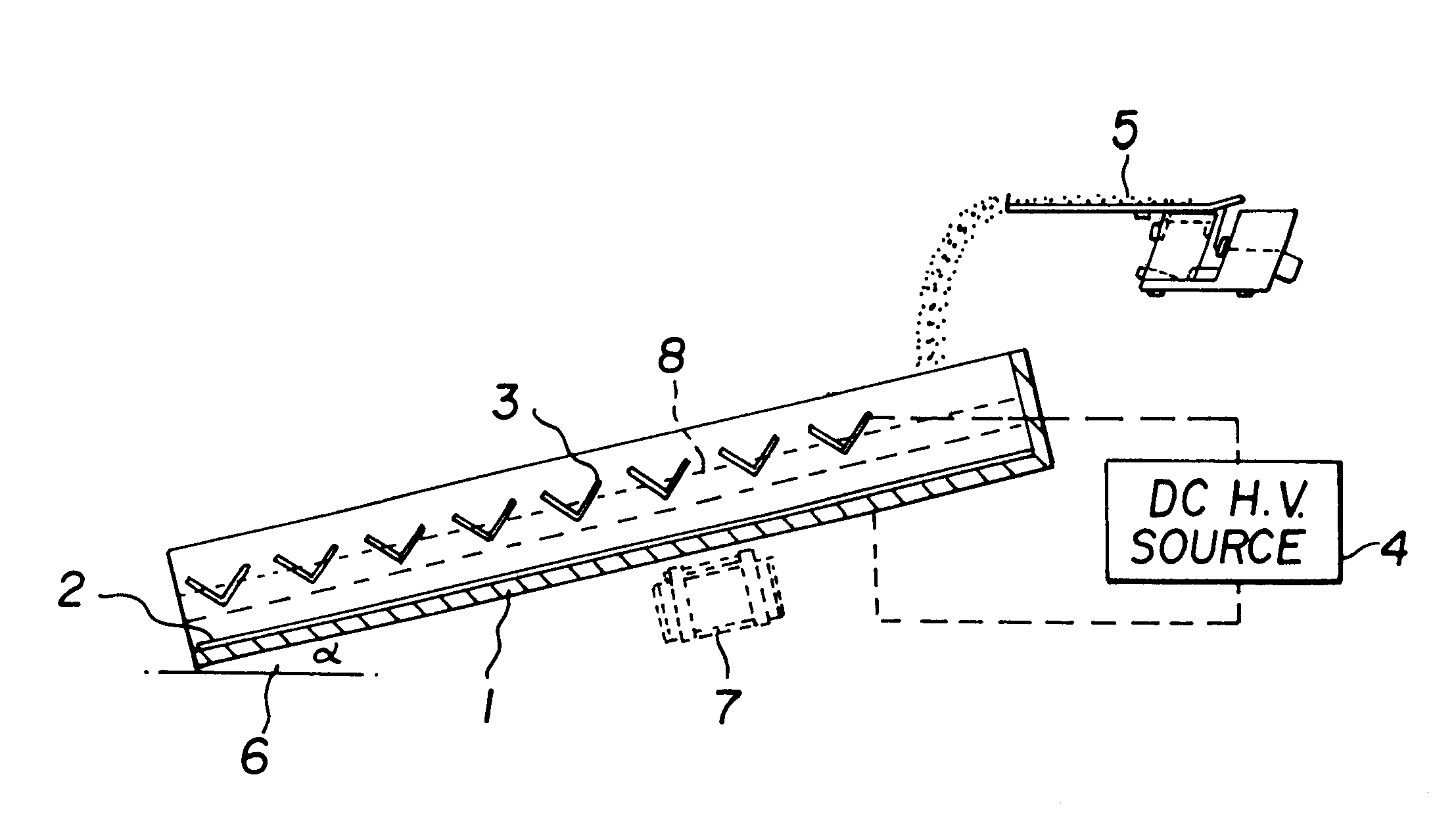
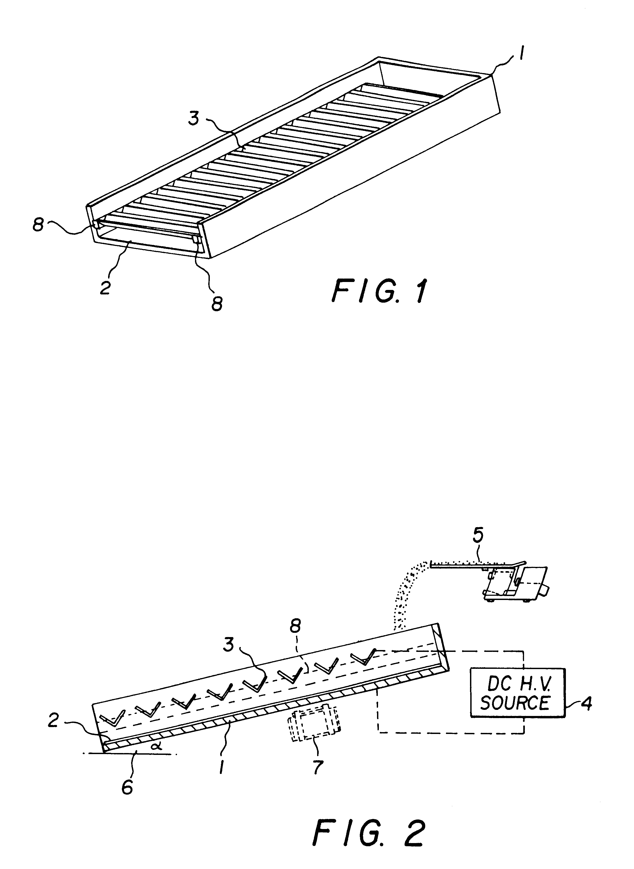
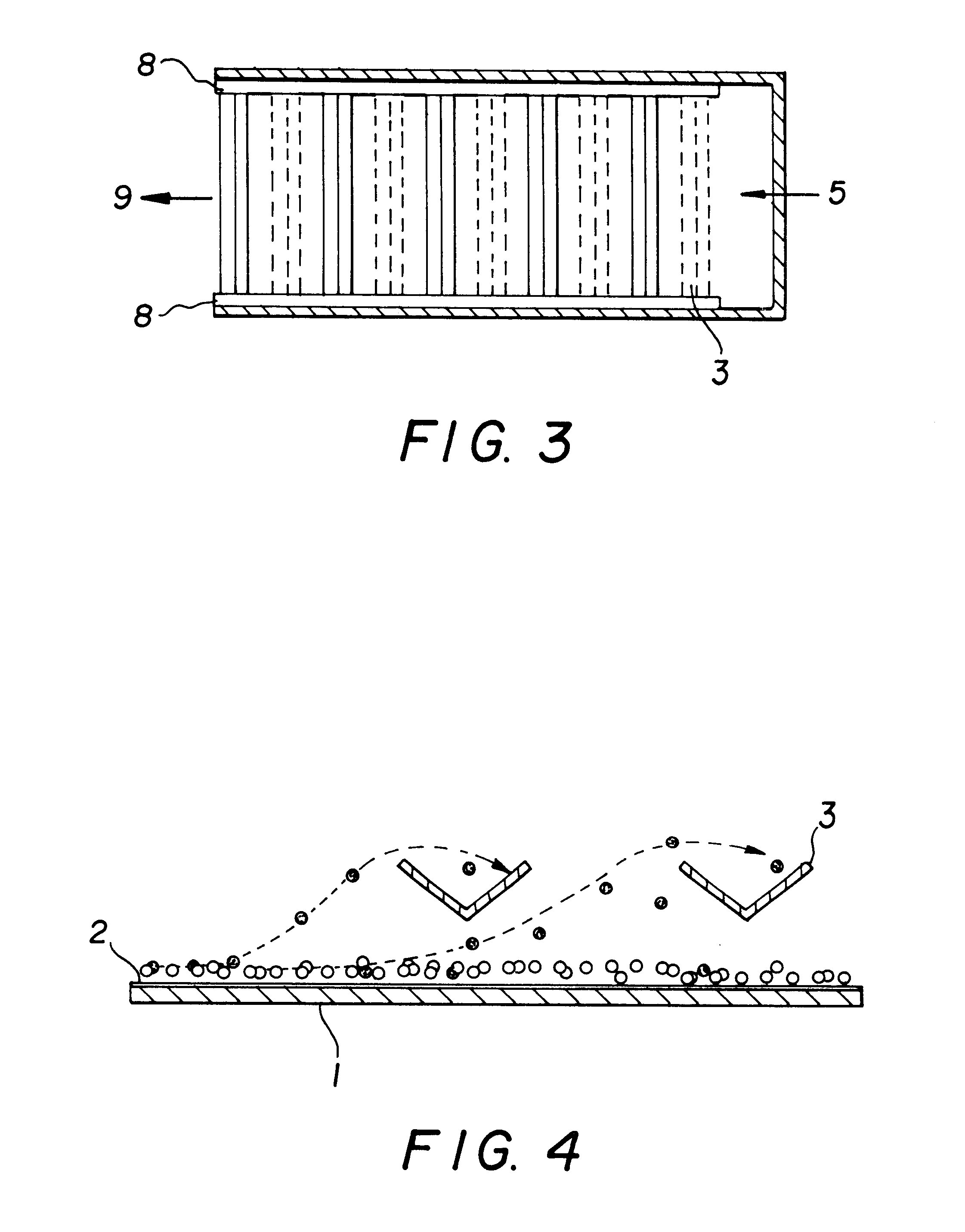
A mixture of particles of different materials 5 is fed to one end of the bottom electrode 2, which may be inclined with an angle 6 to facilitate the materials flow. The angle of slope 6 may be changed to control the feed rate. The whole apparatus is subjected to vibration by means of an electromagnetic vibrator 7 (e.g., Eriez 30S), which is installed underneath the bottom plate 1. The mechanical vibration facilitates: i) forward movement of particles, ii) dispersion of particles to liberate (or detach) them each other, iii) collision of the particles with the bottom electrode to maximize the transfer of electrons between them, and iv) levitation of the charged particles toward the counter electrodes 3.

Problems solved by technology

One of the problems in recycling fly ash as pozzolan is the amount of the unburned carbon left in it.
The unburned carbons in fly ash consume air-entraining agents used in concrete.
They also affect pozzolanic reactivity and weaken the strength of concrete.

Method used


Image

  • Electrostatic method of separating particulate materials
  • Electrostatic method of separating particulate materials
  • Electrostatic method of separating particulate materials

Examples


example 1

In this example, the electrostatic separator developed in the present invention was tested for removing unburned carbon from fly ash. Since carbon is a conductor, it should be charged by conduction and be removed from fly ash. The test sample was received from Korea Fly Ash and Cement Company. It was dry-screened at 200 mesh, and the screen overflow, assaying 26.6% LOI, was used as feed. The tests were conducted by changing the slope of the plate electrode, which determines throughput. Each test was conducted using a 100-g sample. All tests were conducted with the bottom electrode polarized netatively and with the collection troughs above positively. A potential difference of 30 KV was applied between the two electrodes. Under this condition carbon particles were negatively charged and jumped out of the flowing film of fly ash. Since the length of the table used in the tests was short, it was necessary to pass a given sample several times through the separator to obtain a desired LO...

example 2

In this example, the +200 mesh fly ash sample that was used in Example 1 was cleaned by changing the polarities of the electrodes. In one test, the bottom plate was polarized negatively, and in another it was polarized positively. In both tests, the potential difference was set at 30 KV. As shown in Table 2, unburned carbons were removed substantially only when the bottom electrode was polarized negatively. The poor results obtained when the bottom electrode was polarized positively is not clear.

example 3

In this example, the +200 mesh fly ash sample was cleaned five times at 30 KV with the bottom electrode polarized negatively. The results are given in Table 3. It shows that the separation efficiency increased as the number of cleaning stages was increased. This observation may be explained as follows. Although carbon is a condutor, conductivity of the unburned carbon particles present in fly ash may be relativly low. The most likely reason for the low conductivity may be that the surface of the carbon particles may have been oxidized during the process of incomplete combustion in the furnace. The low conductivity may require that unburned carbon particles have multiple contacts with the bottom electrode before they can be sufficiently charged. Nevertheless, the LOI was reduced from 26.2 to 1.3% at a 65.9% recovery after five passes. The recovery can be increased if the rejects are reprocessed.


PUM

PropertyMeasurementUnit
angleaaaaaaaaaa
angleaaaaaaaaaa
electric fieldaaaaaaaaaa

Abstract

A method of separating particulate materials of different properties has been developed. It consists of feeding a mixture of dry, powdered materials to one end of the surface of a planar electrode, which is vibrating to move the particles forward. At least one type of the particulate materials acquires a charge via conduction or triboelectrification. Those particles that acquire charges of the same sign as that of the planar electrode are lifted and collected at the V-shaped counter electrodes installed above. The new separation method is particularly useful for removing unburned carbons from fly ash and any other conducting materials from nonconducting ones.

Description

Two different particulate materials can be separated from each other, if they can be charged differently and placed in an electric field. In one method of separation, corona charges are sprayed over a mixture of conducting and non-conducting particles flowing along the surface of a rotating metal drum. The charges sprayed on the conducting particles dissipate quickly through the drum (which is grounded) and are thrown off, while the non-conducting particles retain the charges and held to the drum surface by image forces. This method is referred to as electrodynamic separation, and is widely used for the beneficiation of potash and heavy minerals.In another, a mixture of conducting and non-conducting particles is fed close to an electrode over a metal plate, which is grounded. The conducting particles are polarized in the electric field near the electrode and lose the charges of the same sign as that of the electrode to the metal plate, thereby acquiring a net charge opposite in sign...

Claims


Application Information

Patent Timeline
Patent Type & Authority Patents(United States)
IPC IPC(8): B03C7/00B03C7/04
CPCB03C7/006B03C7/04Y10S209/92
Inventor YOON, ROE-HOANHAN, OH-HYUNGYAN, ERIC S.PARK, BYUNG-WOOK
Owner YOON ROE HOAN
Learn More