Lift car frame speed limiting device

The technology of a speed limiting device and a car frame is applied in the directions of transportation, packaging, elevators, etc., which can solve the problems of high cost and complicated structure of the speed limiting device, and achieve the effect of low manufacturing cost and simple structure.

Inactive Publication Date: 2013-08-21
三六零安全科技股份有限公司
View PDF4 Cites 6 Cited by
  • Summary
  • Abstract
  • Description
  • Claims
  • Application Information

AI Technical Summary

Problems solved by technology

[0004]The existing car frame speed limiting device is composed of a speed limiting wheel, a tensioning wheel, a speed limiter wire rope, a counterweight and other components. Stop the car frame or car in time when the elevator exceeds the speed, but the existing speed limiting device has a complex structure and high cost

Method used


Image

  • Lift car frame speed limiting device

Examples


Embodiment Construction

[0013] The structure of the present invention will be further described below in conjunction with the accompanying drawings.

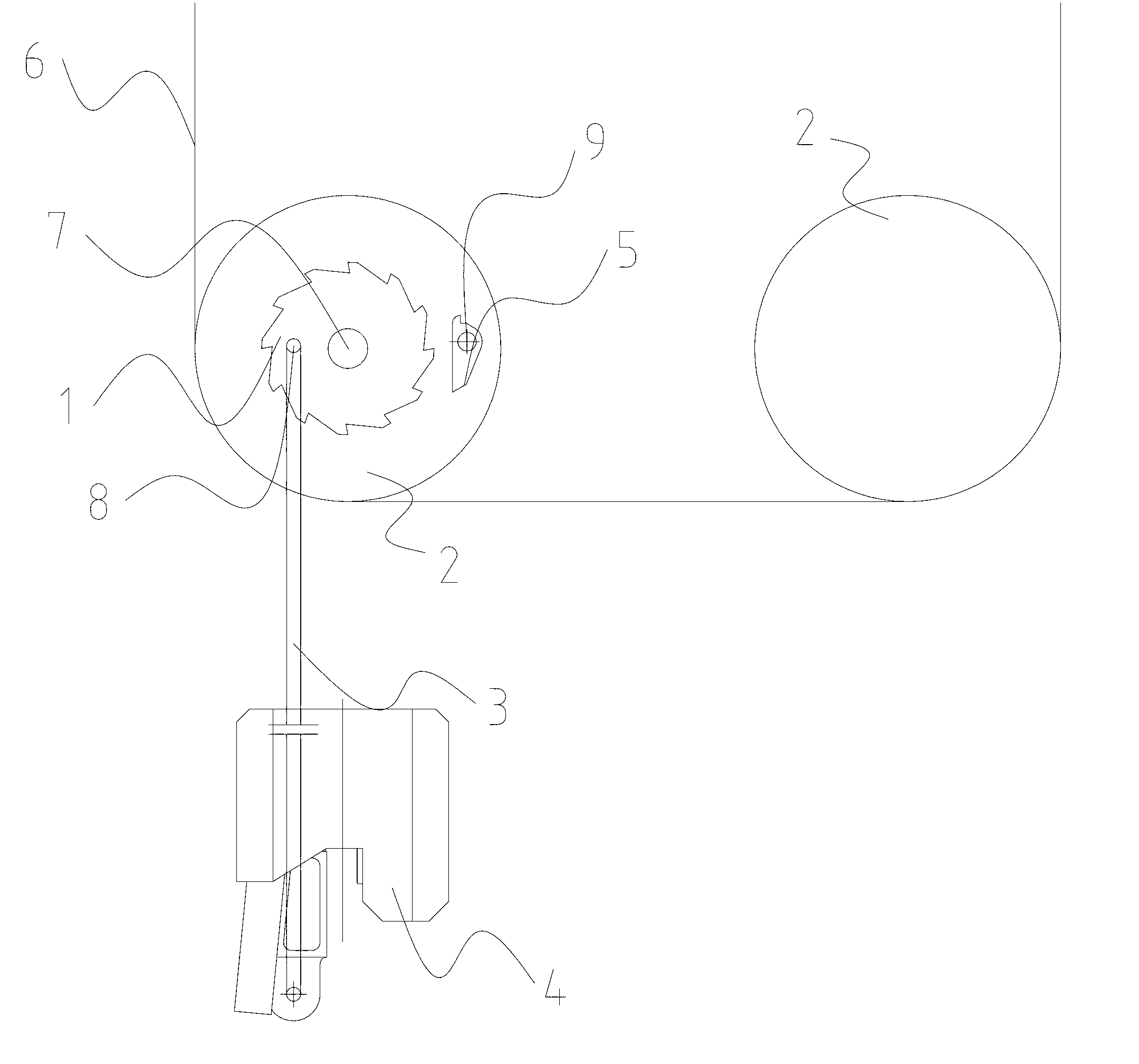
[0014] see figure 1 As shown, a car frame speed limiting device includes a car frame anti-rope pulley 2, a safety gear 4 mounted on the car frame that can stop the car frame or car, and can drive the safety gear 4 to stop the car frame or car. The safety gear lifting rod 3 of the car, the ratchet 1 coaxially arranged with the car frame anti-sheave 2, and the rotation set on the car frame anti-sheave 2 can be rotated when the car frame anti-sheave 2 is overspeed, so as to be inserted into the ratchet 1 The ratchet 5 in the tooth groove, the ratchet 5 is located on the outside of the ratchet 1, although the ratchet 1 and the car frame anti-sheave 2 are coaxially arranged, if there is no cooperation of the ratchet 5, the ratchet 1 and the car frame anti-sheave 2 are Separately and independently arranged, that is, when the car frame anti-sheave 2 rot...


PUM


Abstract

The invention discloses a lift car frame speed limiting device which comprises a ratchet wheel and a pawl, wherein the ratchet wheel is coaxially arranged with a lift car frame diversion sheave, the pawl can be rotatably placed on the lift car frame diversion sheave and is capable of rotating and being inserted into tooth grooves of the ratchet wheel when the lift car frame diversion sheave operates in an over-speed mode. A pair of safety tongs and a draw bar are rotatably placed on the radial surface of the ratchet wheel. When an elevator operates in an over-speed mode, the lift car frame diversion sheave can also rotate in an over-speed mode correspondingly, the pawl rotates and then is clamped inside the tooth grooves of the ratchet wheel, therefore, along with the rotation of the lift car frame diversion sheave, the ratchet wheel rotates correspondingly, the rotating ratchet wheel pulls the safety tongs and the draw bar, the draw bar pulls the safety tongs to enable the safety tongs to move, a lift car can be stopped in time, and a protection role is played. The lift car frame speed limiting device is simple in structure, an over-speed governor steel wire rope, a balancing weight and other components are removed, and manufacturing cost is low.

Description

[0001] technical field [0002] The invention relates to a car frame speed limiting device. [0003] Background technique [0004] The existing car frame speed limiting device is composed of a speed limiting wheel, a tensioning wheel, a speed limiter wire rope, a counterweight and other components, which can stop the car frame or the car in time when the elevator exceeds the speed. The speed limiting device has complex structure and high cost. [0005] Contents of the invention [0006] The object of the present invention is to provide a car frame speed limiting device with simple structure and low cost. [0007] In order to achieve the above purpose, the technical solution adopted by the present invention is: a car frame speed limiting device, including a car frame anti-rope pulley, a safety gear mounted on the car frame that can stop the car frame or the car, and capable of driving the safety gear. The tongs act to stop the car frame or the safety gear pull rod of th...

Claims


Application Information

Patent Timeline
Patent Type & Authority Applications(China)
IPC IPC(8): B66B5/04
Inventor 朱卫华
Owner 三六零安全科技股份有限公司
Why Eureka
Try Eureka