
A flow automatic measurement and control device

A technology of measurement and control device and flow rate, which is applied in the direction of borehole/well valve device, measurement, and production fluid, etc. It can solve the problems of axial thrust bearing damage, valve stem without radial positioning, and low adjustment accuracy, and achieve adjustment accuracy High, improved control accuracy, simple maintenance effect

Active Publication Date: 2016-03-30
ZHEJIANG JINLONG AUTOMATIC CONTROL EQUIP
View PDF6 Cites 0 Cited by
  • Summary
  • Abstract
  • Description
  • Claims
  • Application Information

AI Technical Summary

Problems solved by technology

However, limited by its own structure, the valve stem of the high-pressure flow automatic control device has no radial positioning, and long-term movement will cause damage to the axial thrust bearing and seizure of the worm gear
In addition, there are still defects such as low adjustment accuracy caused by internal leakage of the valve cylinder, and the calibration of the high-pressure flow automatic control device requires the removal of the entire set of equipment for calibration and high labor intensity.

Method used


Image

  • A flow automatic measurement and control device
  • A flow automatic measurement and control device
  • A flow automatic measurement and control device

Examples


Embodiment Construction

[0026] The present invention will be described in detail below in conjunction with the accompanying drawings and embodiments.

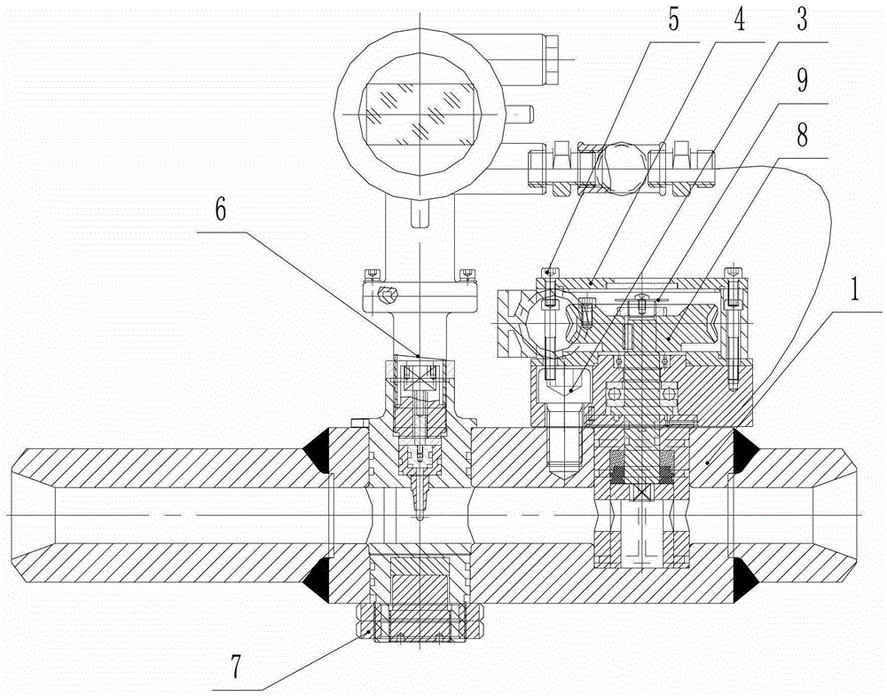
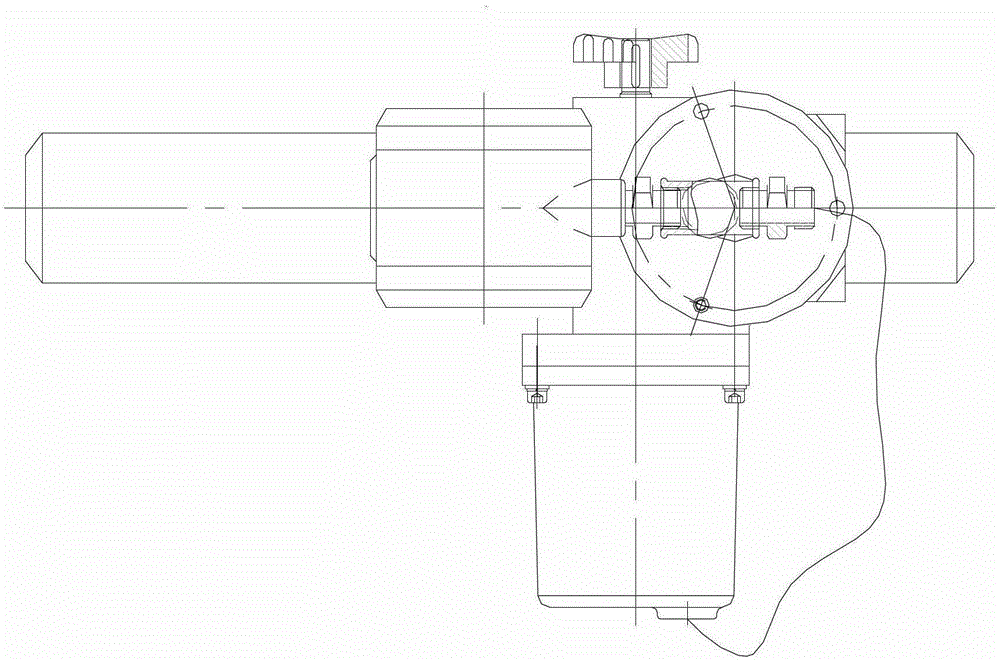
[0027] See figure 1 and figure 2 ,in, figure 1 It is a schematic diagram of the overall structure of the flow automatic measurement and control device of the present invention, figure 2 for figure 1 top view.

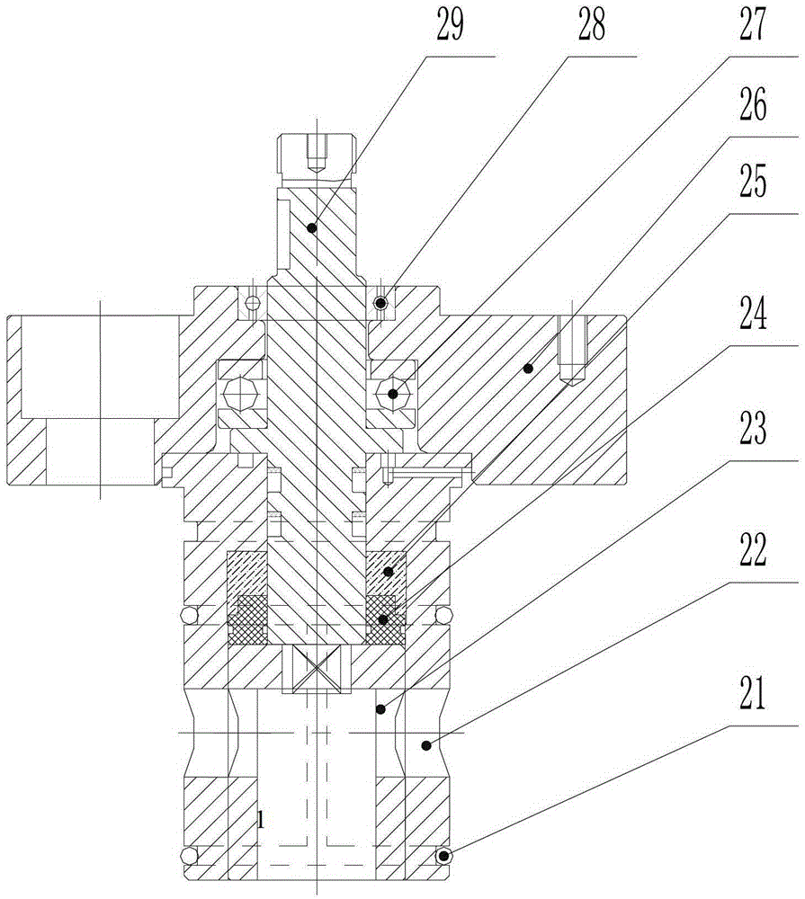
[0028] As shown in the figure, the flow automatic measurement and control device includes a housing 1, a spool assembly, an actuator 8 and a magnetic current meter 6; wherein, the housing 1 has an internal flow channel, and two valves communicating with the internal flow channel The chamber, the shell 1 adopts an integrated structure, the processing error of the flow channel is small, and the measurement accuracy is high; the valve core assembly is arranged in the first chamber to control the flow rate of the internal flow channel through the movement of the valve core 23 to realize opening , closing or opening adjustment; the actuator 8...


PUM


Abstract

The invention discloses a flow automatic measuring and control device. An interior channel is formed in a shell, and two cavities which are communicated with the interior channel are formed in the shell. A spool assembly is arranged in a first cavity to control the through-flow quantity of the interior channel through movement of a spool. An actuator is fixedly arranged on the shell to provide driving force for the movement of the spool. A collection end of a magnetoelectricity flowmeter is arranged in a second cavity to obtain a through-flow quantity signal of the interior channel and output a control instruction to a signal receiving end of the actuator. The spool assembly comprises a valve body, a valve rod, a spool, a thrust bearing and a deep groove ball bearing, wherein an interior through hole is formed in the valve body, a through-flow hole which is communicated with the interior through hole is formed in the lower end of the valve body. The valve rod is arranged in the interior through hole, the upper end of the valve rod stretches out from the valve body. The spool and the valve rod are coaxially fixed in the interior through hole to move corresponding to the through-flow hole under the drive of the valve rod. The thrust bearing is arranged outside the valve rod. The deep groove ball bearing is arranged at the upper side of the valve rod. The flow automatic measuring and control device has the advantages of being convenient to install, easy to operate, strong in anti-jamming capability, and high in regulation accuracy.

Description

technical field [0001] The invention relates to a flow control technology for oilfields, in particular to an automatic flow measurement and control device for high-pressure water injection and polymer injection processes in oilfields. Background technique [0002] In the oilfield water injection pipeline network and polymer injection process, manual control valves are usually used to adjust the flow. As we all know, the pressure of the working medium of water injection and polymer injection pipe network is high, and the flow adjustment is difficult. Especially in manual adjustment, the labor intensity of workers is very high, and the adjustment accuracy and work efficiency are low, which is not conducive to the process effect and economy of water injection and polymer injection. Benefit improvement. [0003] In order to reduce the disadvantages of manual operation, a high-pressure flow automatic control device is used on site in the prior art. However, limited by its own s...

Claims


Application Information

Patent Timeline
Patent Type & Authority Patents(China)
IPC IPC(8): E21B34/16E21B47/00E21B43/20E21B43/22
Inventor 余金海汤健康汪南杰池爱文
Owner ZHEJIANG JINLONG AUTOMATIC CONTROL EQUIP
Learn More