Hydrostatic drive system

一种静液压驱动、低压系统的技术,应用在流体压力致动系统组件、流体压力致动装置、遥控马达等方向

Inactive Publication Date: 2013-08-21
LINDE HYDRAULICS
View PDF7 Cites 10 Cited by
  • Summary
  • Abstract
  • Description
  • Claims
  • Application Information

AI Technical Summary

Problems solved by technology

[0005] However, such additional non-return valves, which can be unblocked, increase the installation outlay and installation space requirement of the drive system, since additional valves are required to compensate differential volume flows and in particular to discharge excess volume flows from the closed circuit.

Method used


Image

  • Hydrostatic drive system

Examples


Embodiment Construction

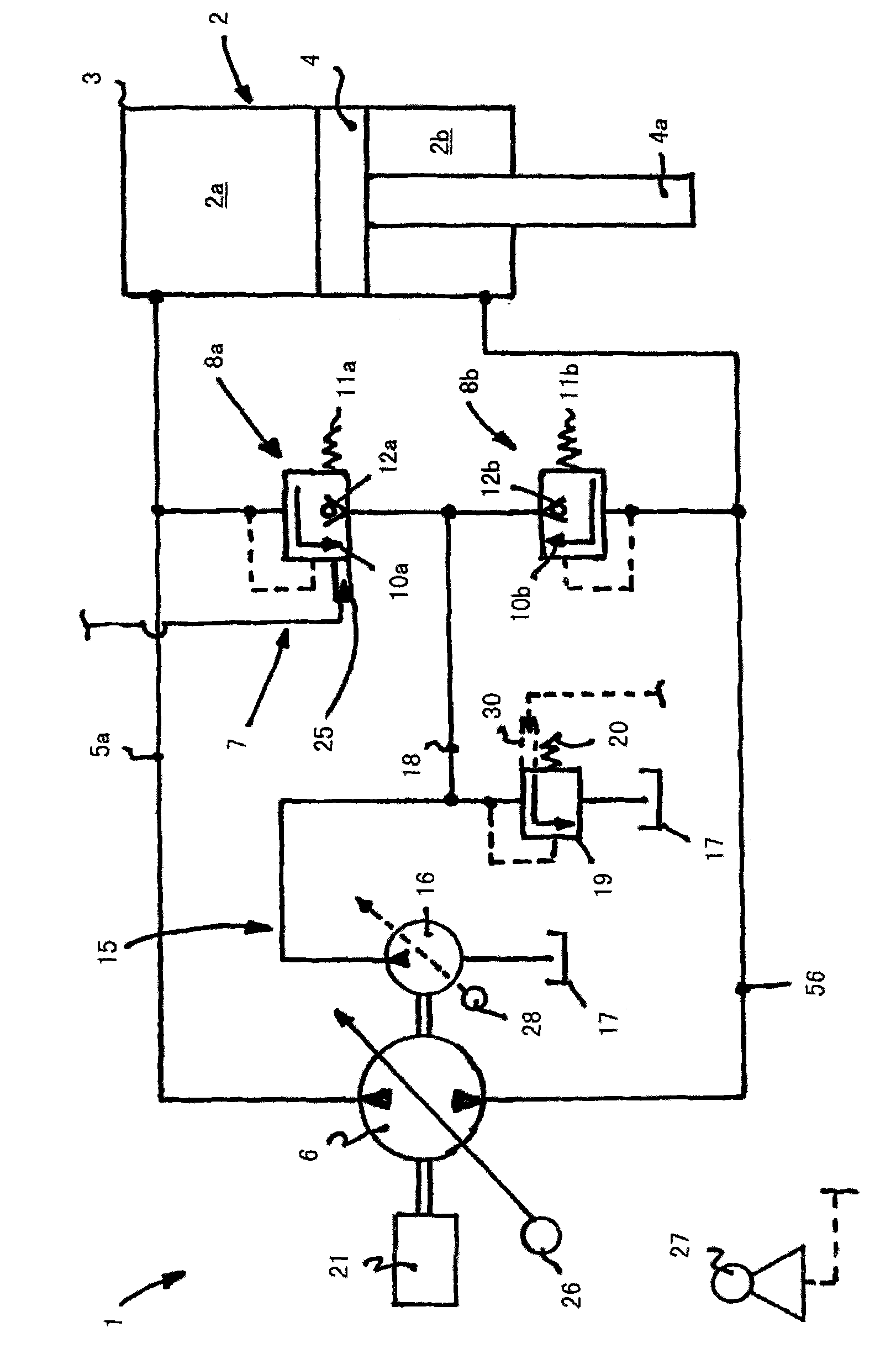
[0019] The drive system 1 comprises a differential hydraulic cylinder 2 operating in a closed circuit as a consumer. The differential hydraulic cylinder 2 comprises a piston which is displaceable longitudinally in a housing 3 and which is provided on one side with a piston rod 4a.

[0020] The differential hydraulic cylinder 2 has a piston-side pressure chamber 2a and a piston-rod-side pressure chamber 2b. The piston-side pressure chamber is connected to the high-pressure pump 6 by means of a first pressure medium pipeline 5a, and the piston-rod-side pressure chamber is connected to a high-pressure pump 6 by means of a second pressure medium. The pipeline 5b is connected with the high-pressure pump 6 . The pressure chambers 2 a , 2 b of the differential cylinder 2 have different volumes depending on the piston rod 4 a arranged in the piston rod-side pressure chamber 2 b.

[0021] The closed circuit formed by the pressure medium lines 5a, 5b and forming a high pressure system ...


PUM


Abstract

A hydrostatic drive system (1) includes a user in the form of a differential cylinder (2) connected in a closed circuit to a high-pressure pump (6). A piston-side compression chamber and a piston-rod-side compression chamber of the differential cylinder are in communication with the high-pressure pump. The closed circuit includes a protection device (7) having first and second protection valve devices (8a,8b) that each includes a pressure relief valve (10a) and an anti-cavitation valve. The pressure relief valve (10a) of the first protection valve device (8a) is provided with an override device (25), by means of which the opening pressure of the pressure relief valve (10a) can be varied. When the high-pressure pump delivers into the piston-rod-side compression chamber (2b), the pressure relief valve (10a) of the first protection valve device is adjusted by means of the override device to a reduced opening pressure and the differential volumetric flow flows out via the pressure relief valve (10a) to a low-pressure system (15).

Description

technical field [0001] The invention relates to a hydrostatic drive system with a consumer configured as a differential hydraulic cylinder, which is connected in a closed circuit to a high-pressure pump, wherein the piston-side pressure chamber of the differential hydraulic cylinder is connected by means of a first pressure medium line and the pressure chamber on the piston rod side of the differential hydraulic cylinder is connected to the high-pressure pump by means of a second pressure medium line, wherein the closed circuit includes a safety device which is assigned to the first pressure medium line and includes a limiter A first safety valve device comprising a pressure valve and a liquid charging valve and a second safety valve device configured to the second pressure medium pipeline comprising a pressure limiting valve and a liquid charging valve are formed, the first safety valve device and The second safety valve device is connected to a low pressure system. Backgro...

Claims


Application Information

Patent Timeline
Patent Type & Authority Applications(China)
IPC IPC(8): F15B11/08F15B7/00F15B21/08
CPCF15B7/006F15B2211/20546F15B2211/20561F15B2211/27F15B2211/5059F15B2211/613F15B15/20
Inventor B·施蒂默尔H·托比亚斯
Owner LINDE HYDRAULICS
Why Eureka
Try Eureka