
Interval oscillation damping method based on input signal switch of FACTS of WAMS and PSS

A technology of input signal and oscillation damping, which is applied in the direction of reducing/preventing power oscillation, etc., and can solve the problems of poor damping effect of interval oscillation

Inactive Publication Date: 2013-08-21
KUNMING UNIV OF SCI & TECH
View PDF3 Cites 3 Cited by
  • Summary
  • Abstract
  • Description
  • Claims
  • Application Information

AI Technical Summary

Problems solved by technology

[0004] The technical problem to be solved by the present invention is to make full use of the FACTS device to overcome the current situation that the PSS has a poor damping effect on the interval oscillation

Method used


Image

  • Interval oscillation damping method based on input signal switch of FACTS of WAMS and PSS
  • Interval oscillation damping method based on input signal switch of FACTS of WAMS and PSS
  • Interval oscillation damping method based on input signal switch of FACTS of WAMS and PSS

Examples


Embodiment approach 1

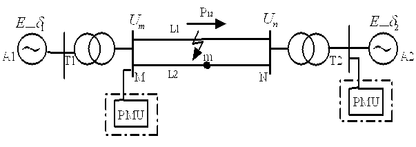
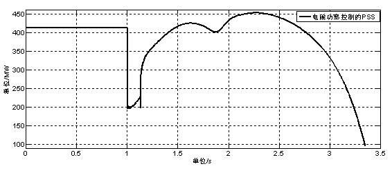
[0084] Implementation Mode 1: As shown in the figure, the two-region system is as follows figure 1 As shown, area 1 and area 2 are connected by double-circuit transmission lines L1 and L2, and WAMS phasor measurement unit PMU is installed at the bus M end to monitor the voltage, current, active power and other power flow conditions on the tie line in real time. Area 1 and area 2 can be composed of one or more equivalent generators respectively, and T1 and T2 respectively represent transformers; area 1 is composed of two equivalent generators with an inertia time constant of 6.5s, and area 2 is also composed of two equal-value generators The inertial time constants of generators are all 6.175 s, each generator side is equipped with PSS, and the threshold value K is obtained according to the generator parameters set 0.05, the length of the connecting line between the two areas is 280km, a three-phase short circuit occurs at the midpoint of line L1, and the fault is removed afte...

Embodiment approach 2

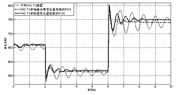
[0095] Embodiment 2: As shown in the figure, using the two-area system in Example 1, each area is replaced by an equivalent machine, and the SSSC is replaced by a parallel FACTS device STATCOM, and the contact is made at the 2s and 6.2s respectively. The voltage of line L2 causes a disturbance, and other parameters are the same as in embodiment 1, and its threshold value K is also obtained according to the parameters of the generator set is 0.05, the data obtained by the data measured by WAMS is 0.055, than the set K set big. Utilize the method and step among the embodiment 1, obtain such as Figure 4 The simulation diagram shown. The dotted line in the figure is the simulation curve for suppressing interval oscillation after adopting the present invention. The meanings of the curves and image 3 The same, will not be repeated here.

[0096] So far, the interval oscillation damping method based on WAMS FACTS and PSS input signal switching has been realized. It can be ...


PUM


Abstract

The invention relates to an interval oscillation damping method based on input signal switch of FACTS of WAMS and PSS, and belongs to the technical field of power system stability and control. When interval oscillation occurs in a call wire L1 of an electrical power system, oscillation occurs in power on call wires between areas, and oscillatory power of the wires is adjusted through a FACTS device. Varying quantity of active power of the wires is calculated according to reactive power provided by FACTS, and a calculated value is variable quantity of electromagnetic power of a generator. The size of damping moment coefficient can be solved according to the relationship between the electromagnetic power of the generator and damping, and at last by comparing the relationship between the solved value of damping moment coefficient and a set threshold value, the phenomenon that a generator electromagnetic power signal or a generator speed signal is adopted by a signal input by PPS is judged. Real data detected by a WAMS system are not needed, only WAMS sends a trigger signal to PSS when the oscillation occurs in the wires, and the trigger signal is not sent when the oscillation does not occur.

Description

technical field [0001] The invention relates to an interval oscillation damping method for switching between FACTS and PSS input signals based on WAMS, and belongs to the technical field of power system stability and control. Background technique [0002] Generator excitation system is an important cause of low-frequency oscillation. Low-frequency oscillation can be classified into local mode and interval mode. between Hz. The interval mode is the oscillation mode that all units in the two power supply areas jointly exhibit, and its frequency range is O. 1~O. 7 Hz, usually the dominant oscillation mode of the system, which is more harmful. Of all the measures to suppress low-frequency oscillations, the addition of PSS is by far the most effective. However, for the low-frequency oscillations that occur in large interconnected systems on the tie lines, the suppression effect of PSS is not ideal. At present, the FACTS additional damping controller is used as a measure to ca...

Claims


Application Information

Patent Timeline
IPC IPC(8): H02J3/24
Inventor 周术明刘志坚宋琪黄蓉杨志华
Owner KUNMING UNIV OF SCI & TECH
Learn More