Equalizer bar bearing assembly

A technology for equalizers and bearings, applied in the direction of bearing components, bearings for rotational motion, bearings, etc., can solve problems such as variable internal pressure, overpressure of pin joint seals, etc.

Inactive Publication Date: 2013-08-21
CATERPILLAR INC
View PDF1 Cites 2 Cited by
  • Summary
  • Abstract
  • Description
  • Claims
  • Application Information

AI Technical Summary

Problems solved by technology

[0003] Movement between the equalizer bar and the track roller frame causes variable internal pressure in the pin joint connecting the equalizer bar to the track roller frame, which can overpressurize the seal in the pin joint

Method used


Image

  • Equalizer bar bearing assembly
  • Equalizer bar bearing assembly
  • Equalizer bar bearing assembly

Examples


Embodiment Construction

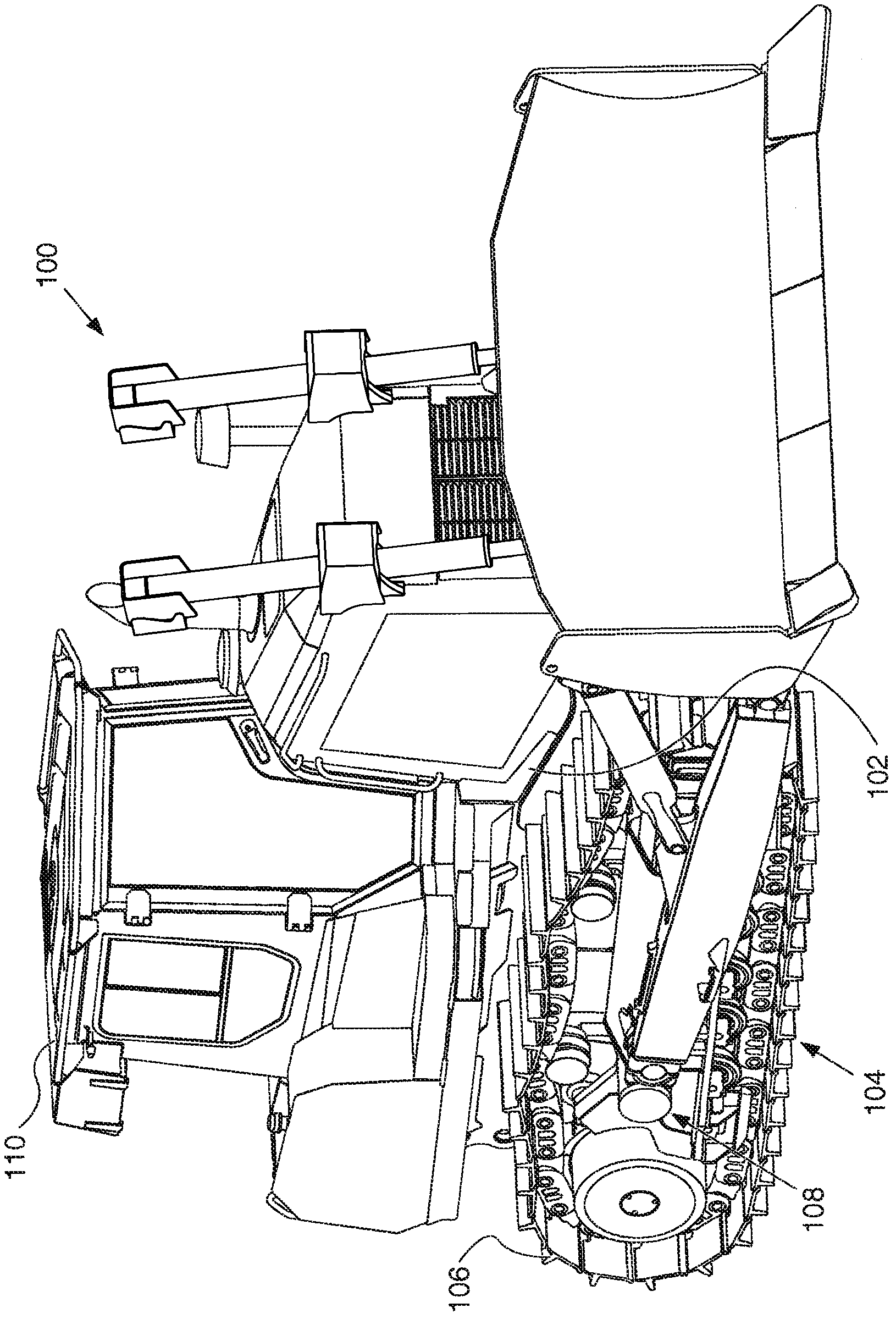
[0017] An exemplary embodiment of machine 100 is in figure 1 shown schematically. Machine 100 may be a motorized machine performing some type of operation associated with an industry such as mining, construction, farming, transportation, or any other industry known in the art. For example, machine 100 may be a track-type tractor, such as figure 1 As shown, it has a frame 102 and a tracked undercarriage 104 operably mounted to the frame 102 . The undercarriage 104 may include a pair of track chains 106 orbiting about a pair of laterally spaced track roller frames 108 .

[0018] A power source, such as an electric motor, a hydraulic motor, or an engine, may be used to actuate undercarriage 104 to move track chains 106 about track roller frame 108 to propel or move machine 100 . Track roller frame 108 may include various undercarriage 104 components, such as track or load wheels, load rollers, idler wheels, and other conventional components, that support and Guides the track ...


PUM


Abstract

The disclosure describes, in one aspect, a bearing (218) assembly including an outer portion and an inner portion adapted to receive an end of a bar. The inner portion includes a fluidic groove extending from a first end (206, 414) of the bearing (218) assembly to a second end (208, 416) of the bearing (218) assembly permitting fluid to flow through the first end (206, 414) and the second end (208, 416).

Description

technical field [0001] The present invention relates generally to an equalizer bar bearing assembly, and more particularly, but not exclusively, to an equalizer bar bearing assembly for connecting a track roller frame to a track-type machine. Background technique [0002] Track machines typically use an equalizer bar between the left and right hand tracks to allow some degree of flexibility in the movement of the tracks relative to the main frame. An equalizer bar is operatively mounted to the main frame, and both ends of the equalizer bar are connected to the left and right hand track roller frames, respectively. The connection between the equalizer bar and the track roller frame must allow a certain degree of movement between the equalizer bar and the track roller frame while being able to withstand significant loads. [0003] Movement between the equalizer bar and the track roller frame causes variable internal pressure in the pin joint connecting the equalizer bar to th...

Claims


Application Information

Patent Timeline
Patent Type & Authority Applications(China)
IPC IPC(8): F16C33/10F16C33/66F16C17/12B62D55/00B62D55/08
CPCB62D55/0842F16C11/02F16C33/1065F16C33/1085F16C23/045
Inventor J·纽克特莱因
Owner CATERPILLAR INC
Why Eureka
Try Eureka