Two-way needle control valve

A technology of through-needle and valve body, which is applied in the direction of charging system, fuel injection device, machine/engine, etc., and can solve the problems of interfering with the lifting member 106 and hindering the response time

Inactive Publication Date: 2014-06-11
INT ENGINE INTPROP CO LLC
View PDF4 Cites 3 Cited by
  • Summary
  • Abstract
  • Description
  • Claims
  • Application Information

AI Technical Summary

Problems solved by technology

However, given the tight dimensional tolerances required for the control valve 100 to provide the necessary sealing, such a configuration may have potential alignment problems, for example, between the upper and lower guides 118, 120 and adjacent portions of the valve bore 108. between
Such alignment issues can interfere with the movement of the lift member 106, which can hinder the response time of the needle 130 to initiate and terminate movement to inject fuel into the combustion chamber

Method used


Image

  • Two-way needle control valve
  • Two-way needle control valve
  • Two-way needle control valve

Examples


Embodiment Construction

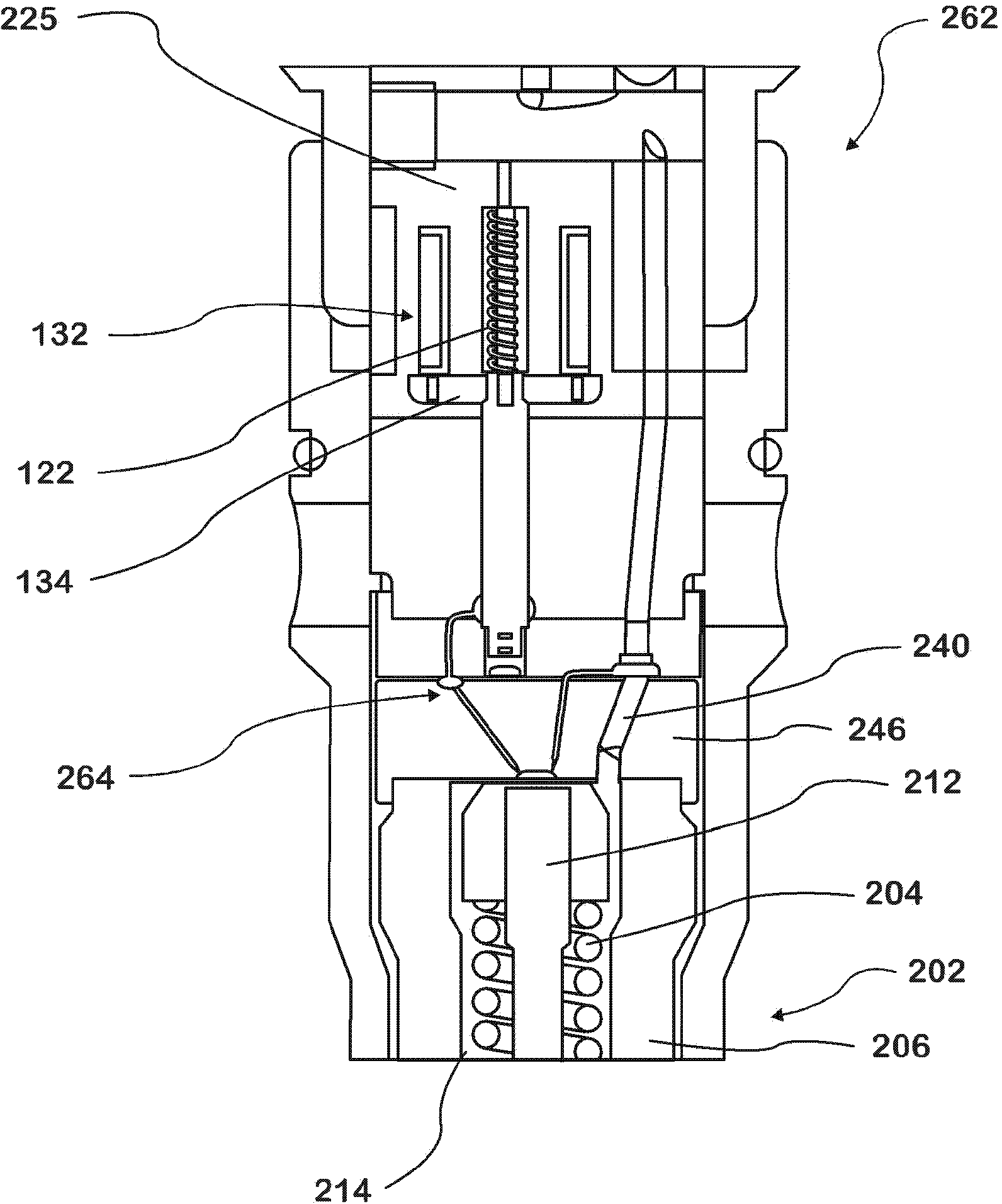
[0014] figure 2 A cross-sectional view of a portion of high pressure fuel injector 262 is shown. The high pressure fuel injector 262 generally includes a nozzle portion 202 . The nozzle portion 202 includes a spring 204 and a nozzle body 206 . The nozzle body 206 and the throttle plate 246 form a longitudinal bore that terminates within the nozzle bore at the end or bottom of the fuel injector 262 . A nozzle valve, such as a needle valve, is configured such that the needle 212 of the needle valve is slidably disposed within the longitudinal bore to move the needle between a first (closed) position and a second (open) position, the first position blocking the nozzle communication between the chamber 214 and the nozzle hole, while the second position opens communication between the nozzle chamber 214 and the nozzle hole. Spring 204 is positioned within nozzle chamber 214 and acts on needle 212 to bias needle 212 to its first (closed) position.

[0015] During operation, fue...


PUM


Abstract

The invention discloses a two-way needle control valve for controlling a needle position of a needle valve in a fuel injector. A lifting structural member is configured to move between an open position and a closed position in a valve hole of a valve body; the valve hole comprises a discharging part; when the valve is at the open position, the discharging part discharges fuel from the valve; the valve comprises a supply pipeline extending to penetrate through at least one part of the valve body; the supply pipeline receives the fuel from a high-pressure fuel pipeline; an inlet throttling pipeline is communicated with the supply pipeline through fluid and conveys the fuel from the supply pipeline to a control cavity in a throttling plate; an outlet throttling pipeline conveys the fuel from the control cavity to a valve body inlet pipeline; the valve body inlet pipeline is configured to convey the fuel to a cavity in the valve hole.

Description

technical field [0001] This application claims the benefit of priority to US Patent Application No. 61 / 567,197, filed December 6, 2011, which is hereby incorporated by reference in its entirety. [0002] The present invention relates to a two-way needle control valve used in a fuel injector. Background technique [0003] High pressure fuel injection systems are often used in internal combustion engines to deliver fuel to the combustion chamber. Fuel may be supplied to a series of unit fuel injectors through a common rail. Fuel injectors typically utilize needle valves to inject fuel into the combustion chamber. When pressurized fuel to be injected into the combustion chamber is supplied to the nozzle chamber of the injector, the pressurized fuel may act on the needle of the needle valve in a direction which attempts to lift the needle to an open position. To balance such forces, the fuel injector may include a region above the needle where a controlled volume of pressuriz...

Claims


Application Information

Patent Timeline
Patent Type & Authority Applications(China)
IPC IPC(8): F02M61/10F02M51/06F02M61/18
Inventor Q·穆罕默德E·汉森K·舒尔茨G·蔡
Owner INT ENGINE INTPROP CO LLC
Why Eureka
Try Eureka