an l-type sio 2 Composite rc-ligbt device with isolation layer

An isolation layer, composite technology, applied in the direction of semiconductor devices, electrical solid devices, electrical components, etc., can solve the problems of complete turn-on obstacles, sudden changes in current and voltage, and great influence on device dynamic characteristics, reducing electric field peaks and improving impact. The effect of high breakdown voltage and strength

Active Publication Date: 2022-02-11
CHONGQING UNIV OF POSTS & TELECOMM
View PDF11 Cites 0 Cited by
  • Summary
  • Abstract
  • Description
  • Claims
  • Application Information

AI Technical Summary

Problems solved by technology

And as the electron current flowing in the N-buffer increases, when V PN It will exceed 0.8V. At this time, the PN junction between the N-buffer and the P-Collector will be opened, and the P-Collector will inject holes into the drift region. At this time, the conversion of the conduction mode will be realized. This process will lead to the Snapback phenomenon. The sudden change of current and voltage on the output curve has a great influence on the dynamic characteristics of the device
This phenomenon will also hinder the complete opening of other devices in the circuit system when the RC-LIGBT is used in parallel at low temperature

Method used


Image

  • an l-type sio  <sub>2</sub> Composite rc-ligbt device with isolation layer
  • an l-type sio  <sub>2</sub> Composite rc-ligbt device with isolation layer
  • an l-type sio  <sub>2</sub> Composite rc-ligbt device with isolation layer

Examples


Embodiment Construction

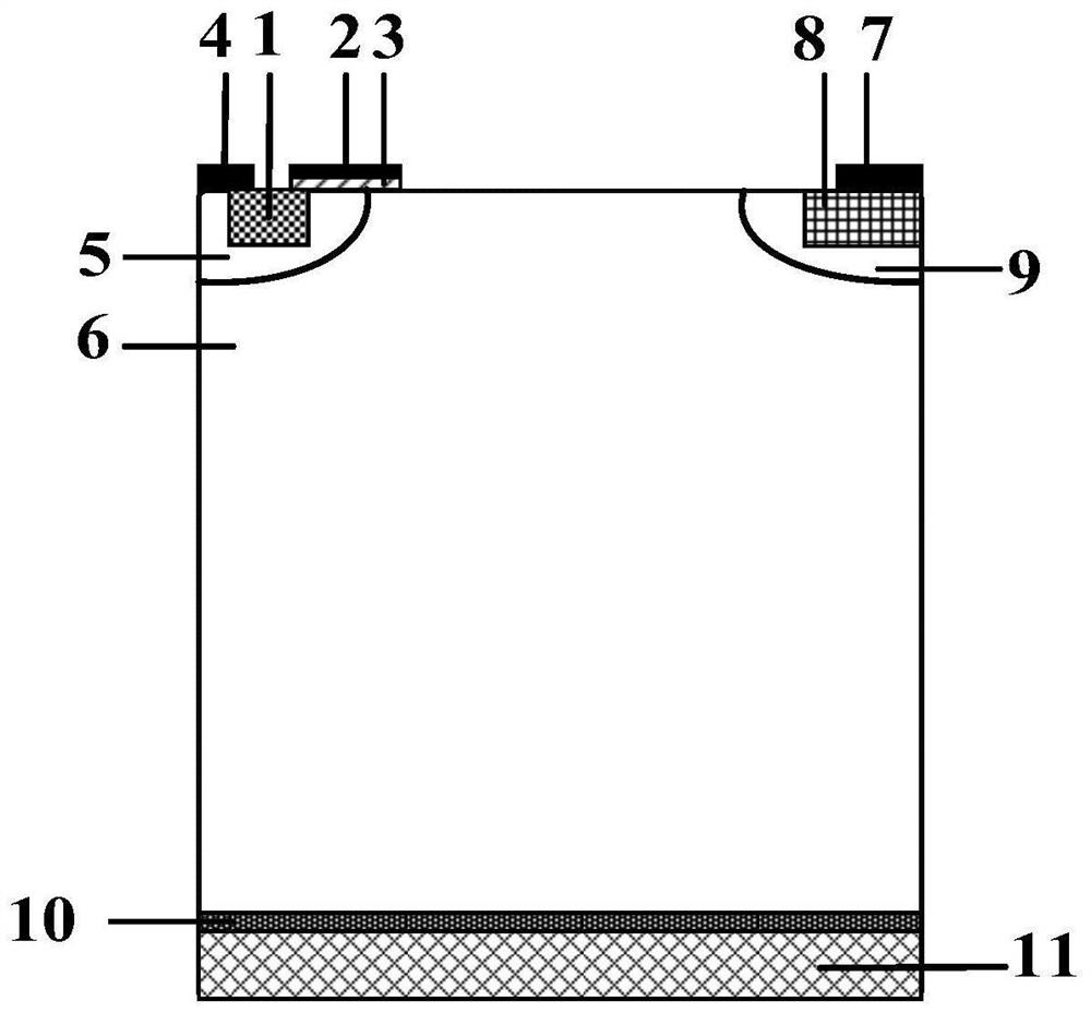
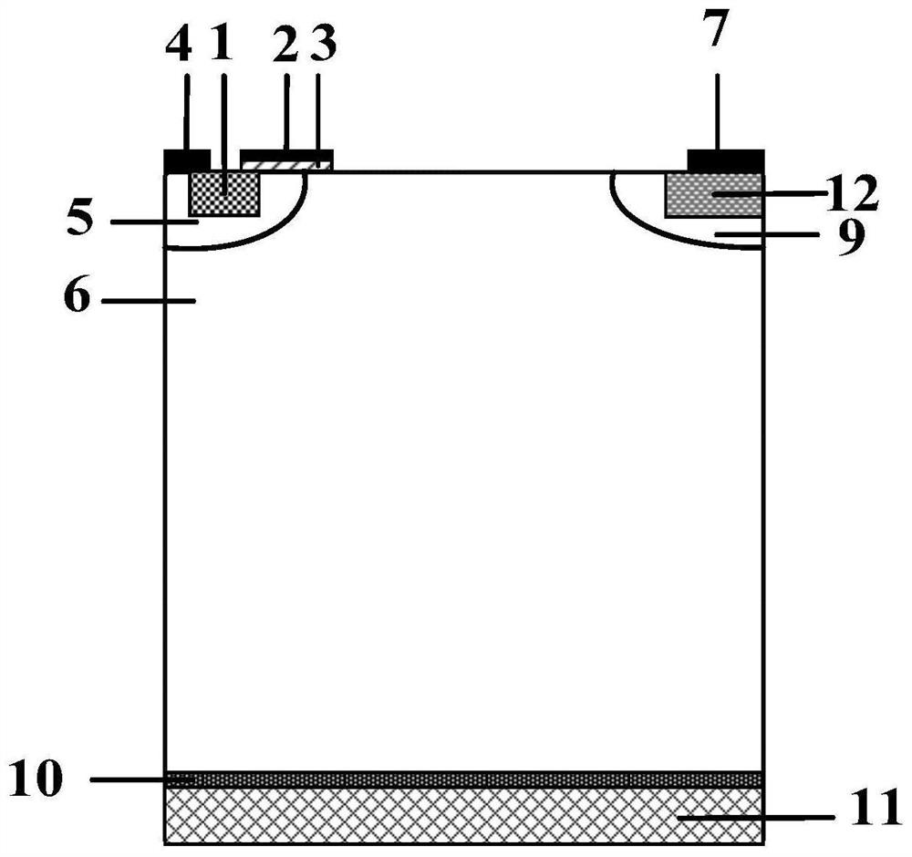
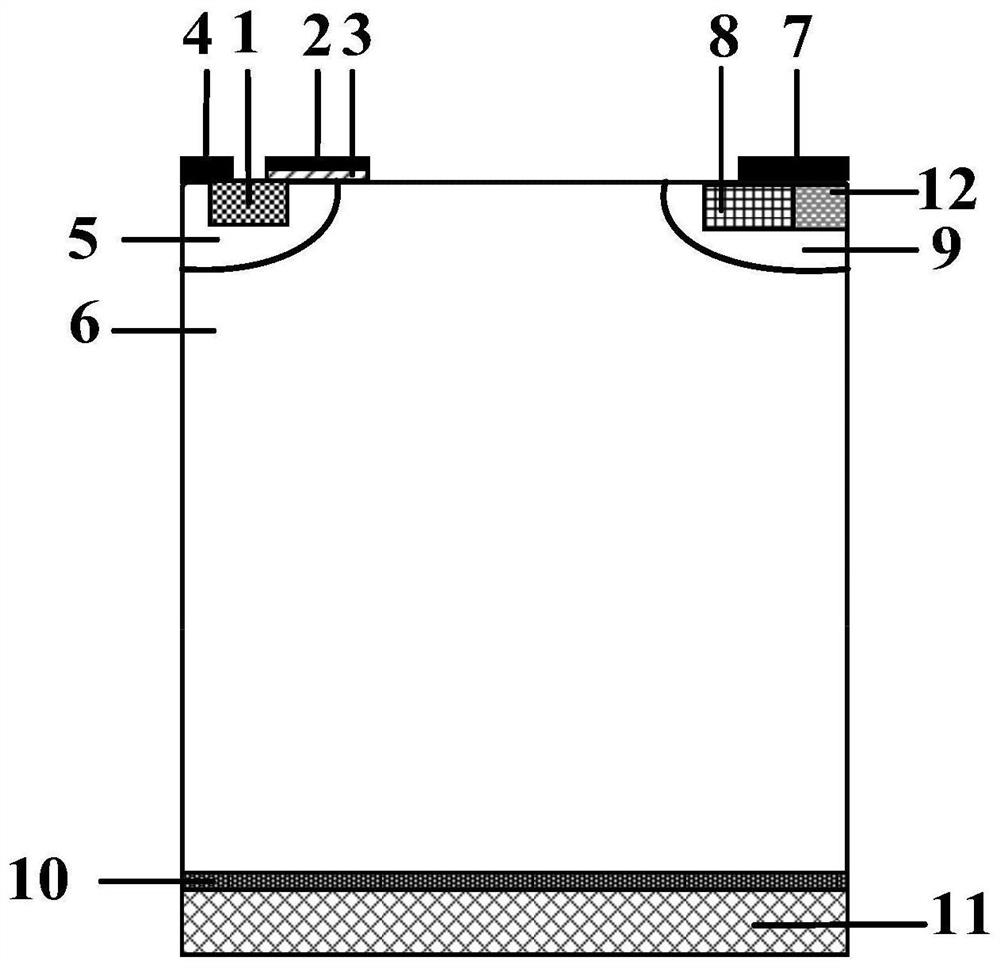
[0041] Embodiments of the present invention are described below through specific examples, and those skilled in the art can easily understand other advantages and effects of the present invention from the content disclosed in this specification. The present invention can also be implemented or applied through other different specific implementation modes, and various modifications or changes can be made to the details in this specification based on different viewpoints and applications without departing from the spirit of the present invention. It should be noted that the diagrams provided in the following embodiments are only schematically illustrating the basic concept of the present invention, and the following embodiments and the features in the embodiments can be combined with each other in the case of no conflict.

[0042] Wherein, the accompanying drawings are for illustrative purposes only, and represent only schematic diagrams, rather than physical drawings, and should...


PUM

PropertyMeasurementUnit
thicknessaaaaaaaaaa
breakdown voltageaaaaaaaaaa

Abstract

The present invention relates to a kind of L-type SiO 2 Composite RC‑LIGBT devices with isolation layer in L-type SiO 2 The isolation layer is divided into LDMOS area and LIGBT area. The working process has the following advantages: (1) reduces the electric field peak of the device, avoids the early breakdown on the device surface, thereby improving the breakdown voltage; (2) During the conversion process of the three modes during conduction, the device is in a stable transition state, and there is no sudden change in current; (3) during reverse conduction, the LDMOS region works independently, N-Collector provides electrons, and P-Collector under emitter reverse bias The body directly injects holes into the drift region, endowing the device with reverse bipolar mode conduction capability. After simulation verification under the same parameter conditions, the breakdown voltage of the composite RC-LIGBT device of the present invention is increased to 206.05V; there is no Snapback phenomenon, and it also has reverse conduction capability.

Description

technical field [0001] The invention belongs to the field of semiconductor power devices, in particular to an L-type SiO 2 Composite RC-LIGBT device with isolation layer. Background technique [0002] LIGBT (Lateral Insulated Gate Bipolar Transistor) based on SOI material has the advantages of good insulation performance, small parasitic capacitance, low leakage current and high integration, and its manufacturing process is compatible with SOI-CMOS process, so it is easy to realize. Therefore, it will become one of the core components of intelligent power integrated circuits and is widely used in home appliances, environmentally friendly automobiles and industrial production. It is a semiconductor power device with great potential in the future market. However, the LIGBT structure is equivalent to two back-to-back diodes during reverse conduction, and the PN junction formed by the P-Collector and N-buffer at the collector is always in a reverse bias state, so LIGBT does not...

Claims


Application Information

Patent Timeline
Patent Type & Authority Patents(China)
IPC IPC(8): H01L29/06H01L29/739H01L27/06
Inventor 陈伟中黄垚李顺黄义贺利军
Owner CHONGQING UNIV OF POSTS & TELECOMM
Why Eureka
Try Eureka