Ditching equipment for smoothing soil pile by utilizing soil compaction degree

A technology of compaction and soil heap, applied in the application, agricultural machinery and implements, plows and other directions, can solve the problems of the soil is not compact in the trenches, waste of power and energy, etc., and achieve the effect of reducing the amount of soil thrown and saving energy.

Inactive Publication Date: 2020-04-10
王仁绪
View PDF0 Cites 0 Cited by
  • Summary
  • Abstract
  • Description
  • Claims
  • Application Information

AI Technical Summary

Problems solved by technology

[0003] Among them, for the control of the strength of the planing parts, the traditional equipment only controls it through the power unit, but the power unit and the planing parts need to be connected, so the power unit cannot directly control the planing strength of the planing parts, so for different The same force is used in all the digging steps, which leads to the waste of power energy; in addition, the soil thrown away by the existing soil throwing equipment will be piled up on both sides of the ditch, which will not only affect the next step of agricultural work, but also cause serious damage. It will make the soil of the ditch not compact and collapse, so a ditching equipment that uses soil compaction to smooth the mound came into being

Method used


Image

  • Ditching equipment for smoothing soil pile by utilizing soil compaction degree
  • Ditching equipment for smoothing soil pile by utilizing soil compaction degree
  • Ditching equipment for smoothing soil pile by utilizing soil compaction degree

Examples


Embodiment Construction

[0023] The following will clearly and completely describe the technical solutions in the embodiments of the present invention with reference to the accompanying drawings in the embodiments of the present invention. Obviously, the described embodiments are only some, not all, embodiments of the present invention. Based on the embodiments of the present invention, all other embodiments obtained by persons of ordinary skill in the art without making creative efforts belong to the protection scope of the present invention.

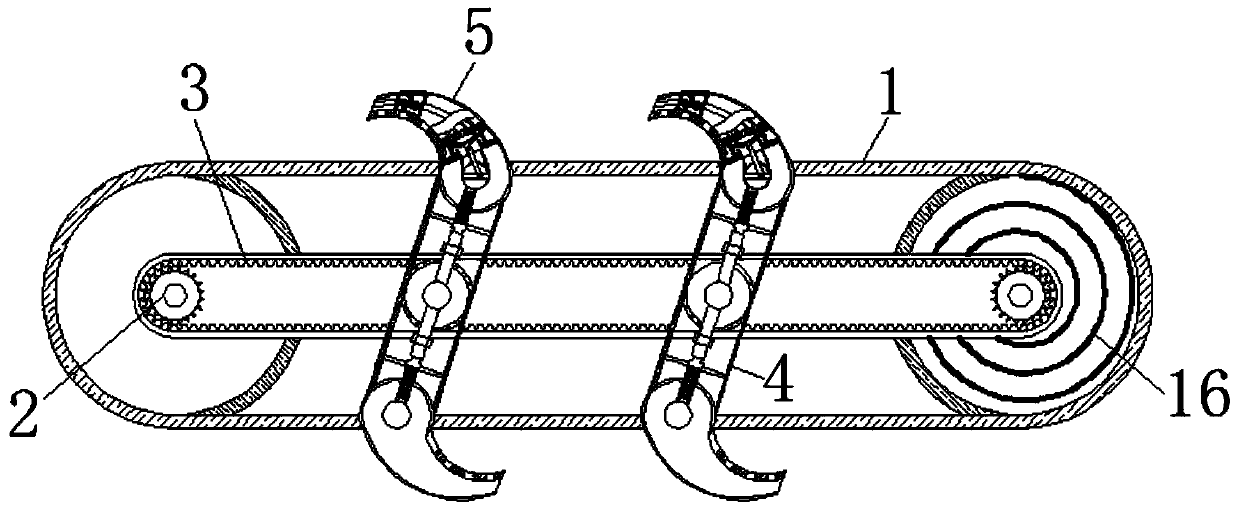
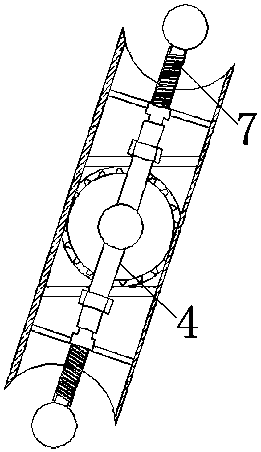
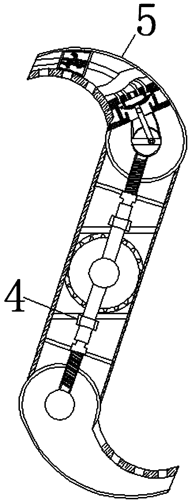
[0024] see Figure 1-7 , a ditching device that uses soil compaction to smoothen the mound, including a conveyor belt 1, the conveyor belt 1 plays the role of a protective cover, and the protection movable chain 3 will not have soil entering, and the internal movable connection of the conveyor belt 1 has Gear 2, the surface of the gear 2 on the right side of the conveyor belt 1 is fixedly connected with a screw rod 16, and the screw rod 16 plays the role of dr...


PUM


Abstract

The invention relates to the technical field of agricultural land ditching and discloses ditching equipment for smoothing a soil pile by utilizing the soil compaction degree. The ditching equipment comprises a transmission belt; a gear is movably connected to the interior of the transmission belt; a moving chain is movably connected to the surface of the gear; warping rods are movably connected tothe surface of the moving chain; arch-shaped plates are movably connected to the two ends of each warping rod; an engaging wheel is fixedly connected to the interior of each arch-shaped plate; and aspring rod is movably connected to the surface of each meshing wheel. By adopting the ditching equipment disclosed by the invention, the transmission belt is moved to enable the arch-shaped plates tobe on the surface of lands to be dug, then a drive part is started to enable the gear to rotate to drive the arch-shaped plates on the surface of the moving chain to gradually move towards the surfaceof the lands and rotates together with the transmission belt in the moving process to transfer the feedback force formed by contact with the lands to the insides of the arch-shaped plates at the lower part, the lever principle is formed, and the digging strength of the arch-shaped plates at the lower part is strengthened, so that the transmission belt and the drive part supplement each other, andthe effects of mutual leveraging according to different soil digging actions and energy consumption conservation are achieved.

Description

technical field [0001] The invention relates to the technical field of agricultural land ditching, in particular to a ditching device for smoothing soil mounds by using soil compaction. Background technique [0002] The chain ditching machine is a new type of efficient and practical chain ditching device, which has the characteristics of high ditching efficiency and smooth ditch, and is of great value in agriculture. The ditching equipment consists of a power unit, a reduction Devices and other parts, wherein the part that determines the shape of the ditch is the chain device. The traditional chain device is provided with a digging part and a soil throwing part, which are convenient to use. [0003] Among them, for the control of the strength of the planing parts, the traditional equipment only controls it through the power unit, but the power unit and the planing parts need to be connected, so the power unit cannot directly control the planing strength of the planing parts,...

Claims


Application Information

Patent Timeline
IPC IPC(8): A01B13/02
CPCA01B13/02
Inventor 王仁绪
Owner 王仁绪
Why Eureka
Try Eureka