Supercharge Your Innovation With Domain-Expert AI Agents!

Apparatus, optical assembly, method for inspection or measurement of an object and method for manufacturing a structure

A technology for optical components and measurement objects, which is applied in 73 fields and can solve problems such as limiting the field of view of the camera, system instability, polarization, etc.

Active Publication Date: 2013-08-21
NIKON CORP
View PDF14 Cites 9 Cited by
  • Summary
  • Abstract
  • Description
  • Claims
  • Application Information

AI Technical Summary

Problems solved by technology

This mirror causes system instability and polarization problems
Existing systems are also not achromatic, so two wavelengths (for example, the pointing beam wavelength and the measuring beam wavelength) cannot be simultaneously focused onto one part in space
Also, existing systems limit the field of view of the camera, which points in the same direction as the lidar

Method used


Image

  • Apparatus, optical assembly, method for inspection or measurement of an object and method for manufacturing a structure
  • Apparatus, optical assembly, method for inspection or measurement of an object and method for manufacturing a structure
  • Apparatus, optical assembly, method for inspection or measurement of an object and method for manufacturing a structure

Examples


no. 1 example

[0046] As described above, the present invention provides an optical assembly that is movable as a unit with a lidar system and is configured to transmit pointing beams and measurement beams from the lidar system, wherein these beams can be directed to the lidar system the targeted target. The present invention is described herein in connection with lidar systems of the type described in U.S. Patents 4,733,609, 4,824,251, 4,830,486, 4,969,736, 5,114,226, 7,139,446, 7,925,134, and Japanese Patent #2,664,399, which are incorporated herein by reference, and in light of these descriptions, the present invention It will be apparent to those skilled in the art that various types of lidar systems can be used to implement the present invention.

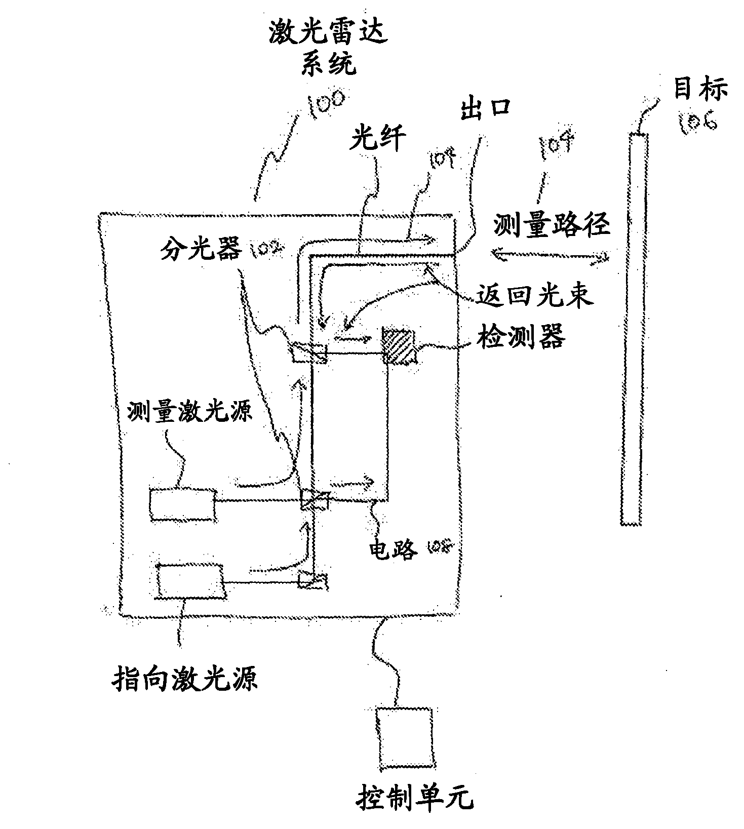
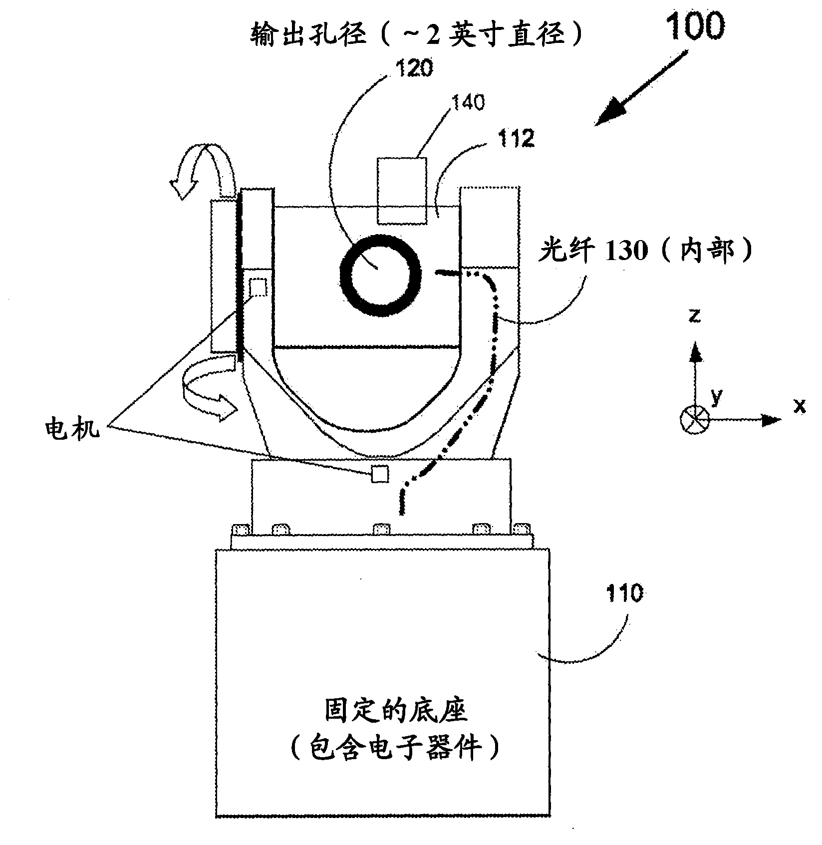
[0047] figure 1 and figure 2 A lidar system including all embodiments disclosed in this application is shown. like figure 1 and figure 2 As shown, the lidar system 100 generates a pointing beam in the visible (e.g., red) wavelength ran...

no. 2 example

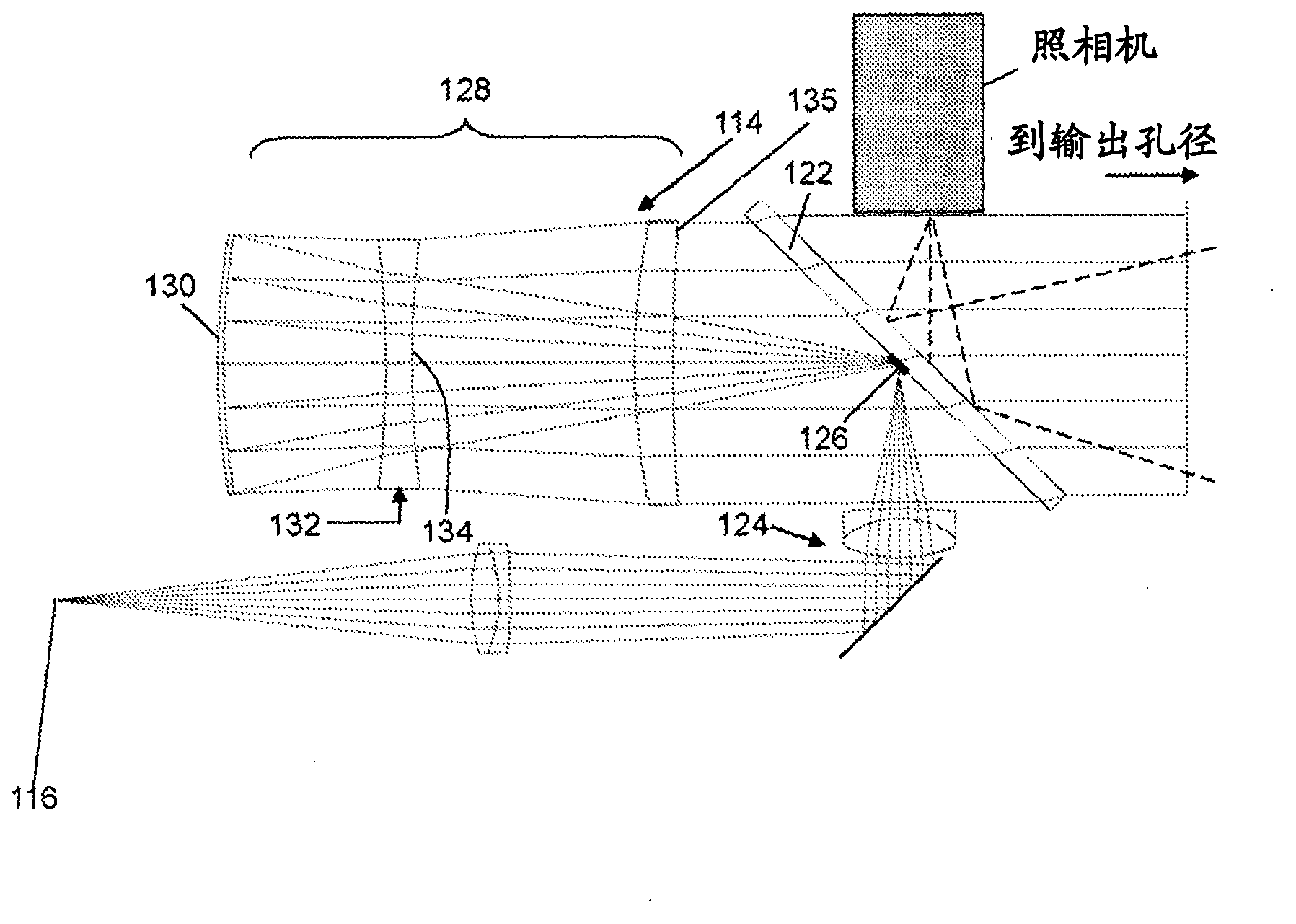
[0067] A second embodiment of the invention would have a lidar system 100 based on a combination of figure 1 and figure 2 Configure and operate on the general principles described above. can be based on Figure 7 a and Figure 7 b recognize some basic features of the optical assembly 114 according to the second embodiment of the present embodiments. Figure 7 The optical assembly of a includes: a light source represented by an optical fiber 130 through which the pointing beam and the measuring beam are guided, a lens 132, a scanning reflector 134 and a Figure 7 In a is a fixed reflector comprising a flat mirror 136 . These components work in conjunction to direct and focus the pointing and measurement beams from optical fiber 130 along line of sight 138 , which preferably coincides with the optical axis of the optical assembly and extends through lens 132 . Optical fiber 130, lens 132, scanning reflector 134, and planar mirror are oriented relative to each other such th...


PUM

PropertyMeasurementUnit
lengthaaaaaaaaaa

Abstract

An optical assembly for a system for inspecting or measuring of an object is provided that is configured to move as a unit with a system, as the system is pointed at a target, and eliminates the need for a large scanning (pointing) mirror that is moveable relative to other parts of the system. The optical assembly comprises catadioptric optics configured to fold the optical path of the pointing beam and measurement beam that are being directed through the outlet of the system, to compress the size of the optical assembly.

Description

[0001] Related application / priority claim [0002] This application is related to and claims priority to Provisional Application Serial No. 61 / 455,768, filed October 25, 2010, which is incorporated herein by reference. Background technique [0003] Lidar is a versatile metrology system that provides non-contact and true single-operator inspection of objects (commonly referred to as targets). LiDAR metrology technology provides object inspection that is particularly useful in obtaining high quality object inspection data in many industries such as aerospace, alternative energy, antennas, satellites, very large castings, and other large-scale applications. [0004] Known concepts of lidar systems are disclosed in US Patents 4,733,609, 4,824,251, 4,830,486, 4,969,736, 5,114,226, 7,139,446, 7,925,134 and Japanese Patent #2,664,399, which are incorporated herein by reference. The laser beam from the lidar system (referred to herein as the "measurement beam") is controlled by the l...

Claims


Application Information

Patent Timeline
Patent Type & Authority Applications(China)
IPC IPC(8): G02F1/33
CPCG01B11/026G01N2021/1793G01S7/4814G01S7/4817G01S7/4818G01N21/01
Inventor E·P·古德温D·M·威廉森D·G·史密斯M·法兰德A·库珀A·罗伯逊B·L·斯塔姆珀
Owner NIKON CORP
Features
  • R&D
  • Intellectual Property
  • Life Sciences
  • Materials
  • Tech Scout
  • Unparalleled Data Quality
  • Higher Quality Content
  • 60% Fewer Hallucinations
Learn More