Diode color ring roll printing device and roll printing method

A diode and printing device technology, applied in printing, printing machines, rotary printing machines, etc., can solve the problems of difficult control of position and density, unfavorable color ring connection, uneven color ring thickness, etc., to achieve easy operation and wide application range , the effect of uniform thickness

Active Publication Date: 2013-08-28
JINAN JINGHENG ELECTRONICS
View PDF10 Cites 7 Cited by
  • Summary
  • Abstract
  • Description
  • Claims
  • Application Information

AI Technical Summary

Problems solved by technology

[0005] 1. The rolling printing of the traditional color circle is to use a pen to rotate and brush manually. The above method requires a single operation and is time-consuming and laborious, which is not conducive to the ring connection of the color circle.
[0006] 2. There is also a color ring rolling printing equipment, which includes ink cartridges, multiple ink distribution wheels, printing wheels and reclaiming wheels. The retrieving wheels are equipped with magnets, and the diodes are adsorbed on the retrieving wheels through the magnets. The route is that a plurality of ink distribution wheels roll opposite to make the ink transfer to the printing wheel, and then the magnet inlaid with the take-up wheel absorbs the device and uses the rotation of the printing wheel to perform color ring rolling. The above method is automatic rolling printing, although it solves the problem of manual printing. coated efficiency issues, but only for Figure 4 A diode with a round lead wire is shown, the lead wire must be round and made of iron-nickel alloy, which is a magnetic material, so that it can be attracted by a magnet

Method used


Image

  • Diode color ring roll printing device and roll printing method
  • Diode color ring roll printing device and roll printing method
  • Diode color ring roll printing device and roll printing method

Examples


Embodiment Construction

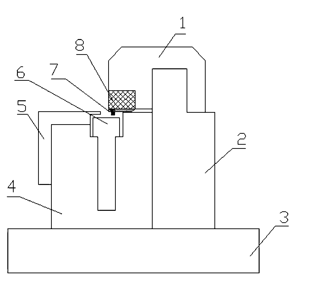
[0022] Such as figure 1 A diode color ring rolling printing device shown includes a printing block 1 , a linear guide rail 2 , a bottom plate 3 , a mold carrier 4 , a pressing plate 5 , a mold 6 , a color ring stamp mold 7 and a decompression pad 8 .

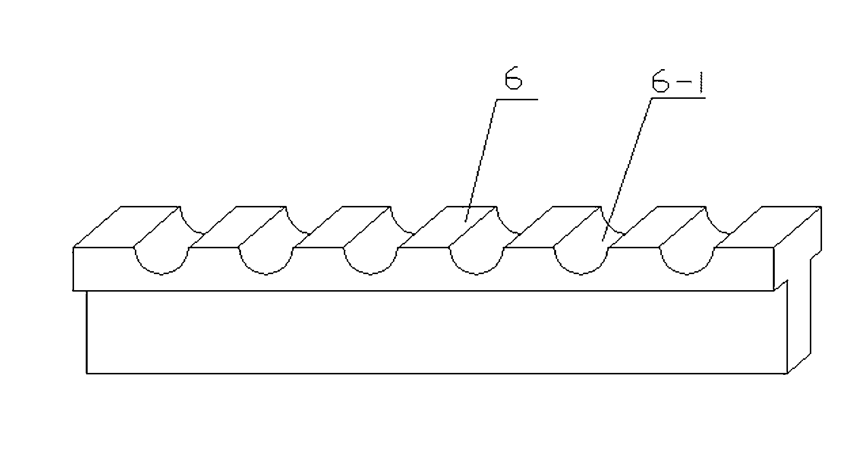
[0023] Such as figure 2 As shown, the mold 6 is a T-shaped block with a certain length, and the top surface of the mold 6 is provided with a plurality of arc-shaped grooves 6-1 that can accommodate a glass bulb 15 of a diode, and the arc-shaped grooves 6-1 run through Mold 6, the length of the arc groove 6-1 is less than the distance between the two terminals of the diode, there is a T-shaped groove on the mold carrier 4, and the mold 6 is inserted in the T-shaped groove on the mold carrier 4, the mold 6 There is a certain gap between both sides of the upper end and the mold carrier 4, forming a space that can accommodate the terminals of the rolling diodes, and the guiding direction of the linear guide rail 2 is perpendicula...


PUM


Abstract

The invention discloses a diode color ring roll printing device and a roll printing method. At least one glass-bulb arc-shaped groove capable of containing one diode is formed in the top face of a die, the arc-shaped groove penetrates through the die, the length of the arc-shaped groove is smaller than the distance between two wiring terminals of the diode, the die is arranged on a die carrier, space for containing the wring terminals of the rolling diode is formed in the two sides of the arc-shaped groove and outside the die, the guiding direction of a linear guiding rail is perpendicular to the axial direction of the arc-shaped groove, and the printing device is arranged on the linear guiding rail in a sliding mode. According to the roll printing method, the diode color ring roll printing device is adopted. Before the diode color ring roll printing device performs roll printing, the diode is only needed to be installed in the arc-shaped groove, and the two wiring terminals of the diode are located outside the groove; the roll printing method, the diode color ring roll printing device can be adopted for both a round leading wire diode and a square leading wire diode to perform the roll printing, and material of leading wires is not limited.

Description

technical field [0001] The invention relates to a diode color ring rolling printing device, and also relates to a diode color ring rolling printing method. Background technique [0002] like Figure 4 Shown, the diode of circular lead comprises glass bulb 15, chip and two circular lead 13, and color circle 14 is arranged on glass bulb 15, as Figure 5 As shown, the diode of the square lead includes a glass bulb 15, a chip and two square leads 16, the glass bulb 15 is a round glass tube, the round lead 13 and the square lead 16 all include cylindrical electrodes and terminals, and the wiring of the round lead 13 The cross section of the terminal is circular in the direction perpendicular to the diode axis, and the terminal of the square lead wire 16 is square in cross section in the direction perpendicular to the diode axis. [0003] According to the process regulations, it is necessary to roll the color ring on the glass bulb of the diode to distinguish the positive and ne...

Claims


Application Information

Patent Timeline
Patent Type & Authority Applications(China)
IPC IPC(8): B41F17/20
Inventor 王培祥戚涛邵亦军梁瑞芳朱海涛
Owner JINAN JINGHENG ELECTRONICS
Why Eureka
Try Eureka