Depth image based pavement detection system

A road surface detection and depth image technology, applied in image enhancement, image analysis, image data processing and other directions, can solve the problems of discrete, uneven illumination, loss of depth information, i.e. distance value, etc.

Inactive Publication Date: 2013-08-28
JIANGSU UNIV OF SCI & TECH
View PDF4 Cites 20 Cited by
  • Summary
  • Abstract
  • Description
  • Claims
  • Application Information

AI Technical Summary

Problems solved by technology

Responsive road surface roughness testing equipment is generally simple in structure and cheap in price, but it cannot directly obtain the profile curve shape of the road surface, and its detection values ​​do not have time stability, and frequent calibration is required
Section-type road surface roughness testing equipment can directly obtain the curve shape of the longitudinal section of the road surface, but the section-type road surface roughness testing equipment has a complex structure and is expensive, and most of them are discrete tests, that is, several section values ​​​​along the longitudinal direction are used to measure the overall The level of roughness of the road reflects only an approximate value
In addition, most of the current roughness detection devices can only measure the roughness; or integrate multiple measurement systems together to simultaneously measure other road surface information such as damage, ruts, etc.
However, the information between the systems is not shared, and there are problems of waste of resources and low efficiency.
[0004] The damage detection system is mostly based on the images obtained by the CCD camera, which is highly dependent on the external lighting conditions such as light intensity, light source orientation and occlusion, and there will be a lot of uneven lighting and shadows in the road surface image, which increases the difficulty of damage detection
At the same time, factors such as road markings will have a certain impact on the detection
In addition, the depth information, that is, the distance value, is lost when the camera converts the 3D scene into a 2D image through the imaging system

Method used


Image

  • Depth image based pavement detection system
  • Depth image based pavement detection system
  • Depth image based pavement detection system

Examples


Embodiment Construction

[0032] Below in conjunction with specific embodiment, further illustrate the present invention, should be understood that these embodiments are only used to illustrate the present invention and are not intended to limit the scope of the present invention, after having read the present invention, those skilled in the art will understand various equivalent forms of the present invention All modifications fall within the scope defined by the appended claims of the present application.

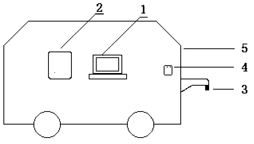
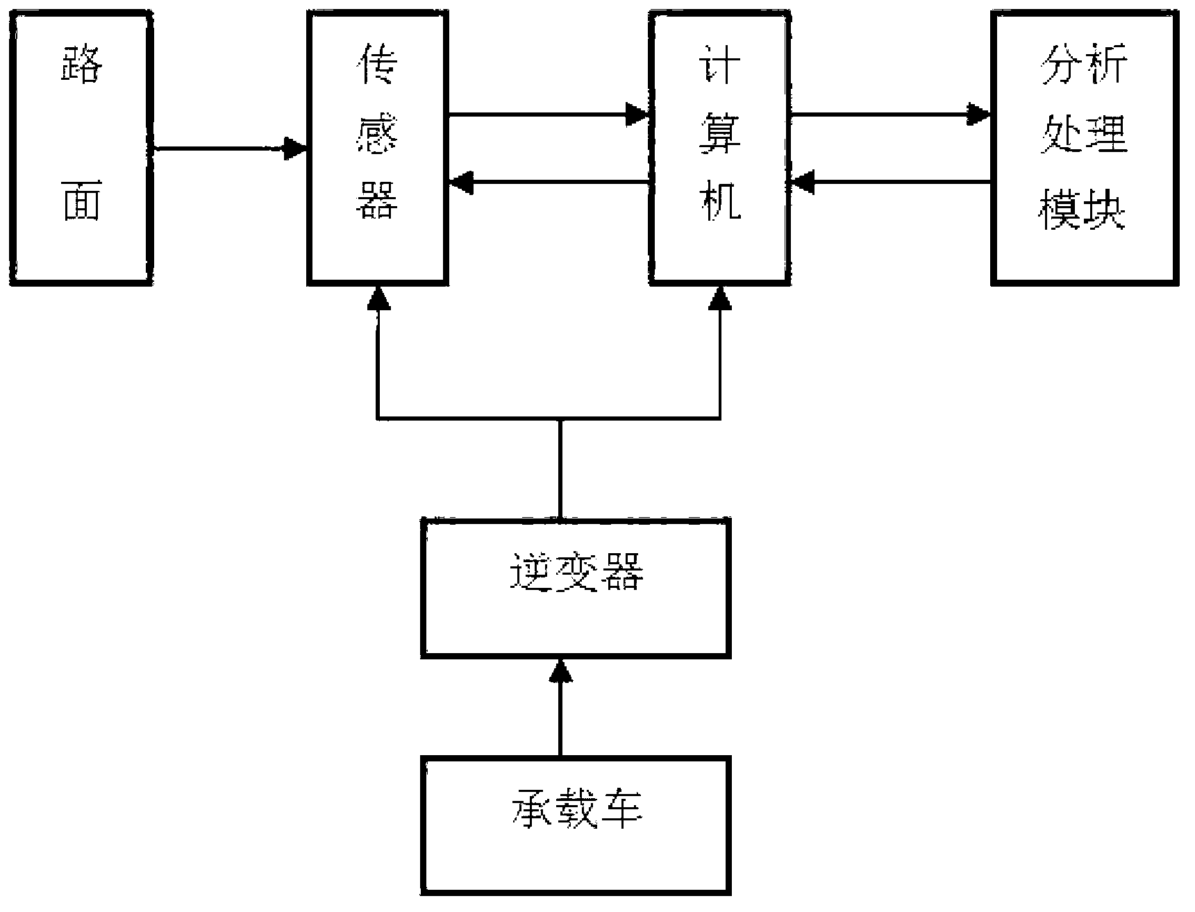
[0033] Such as figure 1 As shown, the road detection system based on the depth image includes a computer 1 , an analysis and processing module 2 , a kinect sensor 3 , an inverter 4 and a vehicle 5 . kinect sensor 3, computer 1, inverter 4, are installed on the carrying vehicle 5, and wherein kinect sensor 3 is located at the outside of carrying vehicle 5, and kinect sensor 3 is connected with computer by data line, and inverter is computer, kinect sensor 3 Provide power.

[0034] Such as figur...


PUM


Abstract

The invention discloses a depth image based pavement detection system. The system comprises a computer, an analyzing and processing module, a kinect sensor, an inverter and a vehicle; the kinect sensor, the computer and the inverter are installed on the vehicle, and the inverter provides power for the computer and the inverter; the kinect sensor is used for acquiring pavement depth image data and transmits to the computer; and the computer calls the analyzing and processing module, analyzes and processes the obtained pavement depth image data to obtain unevenness and damage information, and displays and stores the unevenness and damage information. The pavement unevenness and damage information is obtained through pavement depth images. The system has the advantages of simple operation, convenient use and maintenance, time and money saving, and provision of picturesque pavement information for people.

Description

technical field [0001] The invention relates to a road surface detection system based on a depth image, belonging to the technical field of road surface information detection. Background technique [0002] Pavement quality has an important impact on driving comfort, safety, economy and road life cycle. The management and maintenance of pavement is inseparable from the detection of pavement information. Road surface information detection includes unevenness detection, damage detection, etc. [0003] At present, there are mainly two types of road surface roughness detection devices: response type and cross-section type. Responsive pavement roughness testing equipment is generally simple in structure and cheap in price, but it cannot directly obtain the profile curve shape of the pavement, and its detection values ​​are not time-stable and require frequent calibration. Section-type road surface roughness testing equipment can directly obtain the curve shape of the longitudin...

Claims


Application Information

Patent Timeline
Patent Type & Authority Applications(China)
IPC IPC(8): E01C23/01G06T7/00G06T5/50
Inventor 李忠国王凯唐炜陈超王佳徐家乐刘庆华
Owner JIANGSU UNIV OF SCI & TECH
Why Eureka
Try Eureka