
A vertical axis wind power generator

A technology of wind power generation device and vertical axis, which is applied in the direction of wind power generation, wind power engine, wind power motor combination, etc. It can solve the problems of high wind speed requirements, limit the scale of wind power generation device, limit the installation range of wind power generation device, etc., and achieve the improvement of power generation efficiency , Improve space utilization, expand the effect of installation and use

Inactive Publication Date: 2015-12-09
BEIJING ZHONGTIAN JIANZHONG ENG DESIGN
View PDF6 Cites 0 Cited by
  • Summary
  • Abstract
  • Description
  • Claims
  • Application Information

AI Technical Summary

Problems solved by technology

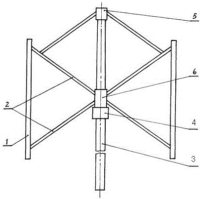
[0003] The vertical axis wind power generation device with the above-mentioned structure has the disadvantage that the operating space is too large. The distance from the blade 1 to the vertical support shaft 3 is usually several meters. In this space, due to the installation of the connecting piece 2, it cannot be used at all, and it is difficult to communicate with it. Building integration, such as the open area that can only be installed on the top floor of the building, limits the installation range of wind power plants
In addition, since the blades of the wind power generation device in the prior art are all supported on the vertical support shaft at the center, this structure limits the scale of the existing wind power generation device, making it impossible to make the existing wind power generation device very big
This is because, if the structure of the wind power generation device in the prior art is made too large, the problem of eccentricity will be more serious, which will easily lead to safety problems
In addition, the vertical axis wind power generation device with the existing structure has relatively high requirements for wind speed, and it is difficult to capture energy at low wind speeds.

Method used


Image

  • A vertical axis wind power generator
  • A vertical axis wind power generator
  • A vertical axis wind power generator

Examples


Embodiment 1

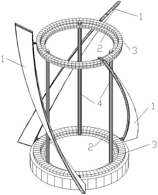
[0028] Such as figure 2 As shown, the first embodiment of the vertical axis wind power generation device of the present invention includes a first blade group composed of blades 1, a rotating member for the blades 1 to rotate around, and a connecting body 3 for movably installing the blade 1 on the rotating member. And the generator (not shown), also includes the support body 4, under the action of wind, the blade 1 rotates around the rotor to drive the generator to generate electricity.

[0029] Such as figure 2 As shown, the number of blades 1 in the first blade group is not less than two, and in this embodiment is three. The rotating part is an annular track 2 , and the connecting body 3 is annular. The blades 1 in the first blade group are fixed on the outside of the connecting body 3 and evenly distributed around the annular track 2 . The circular track 2 is a circular track, and the connecting body 3 is supported on the upper surface of the circular track. On the opp...

Embodiment 4

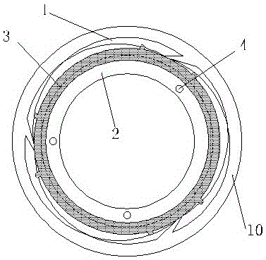
[0041] The way of installing the rotating shaft in the fourth embodiment is as follows: a vertical shaft 11 is installed in the middle of the wind power generation device in the first embodiment, and the upper end of the vertical shaft 11 passes through the annular track 2 and the annular connecting body 3, and the rotating shaft 5 The movable sleeve is on the top of the vertical shaft 11, and driven by the wind, the second blade group and its rotating shaft 5 rotate around the vertical shaft 11. The lower end of the second blade group is horizontally provided with an annular body 12 , and the lower end surface of the annular body 12 is provided with a recess for accommodating the connecting body 3 , and the connecting body 3 is accommodated therein. The magnets as the generator stator and the coils as the generator rotor are respectively arranged on the annular body 12 and the connecting body 3 . Under the action of wind force, the first blade set and the second blade set mov...


PUM


Abstract

A vertical-shaft wind power generation device comprises a first blade group composed of blades, a rotation part for the blades to rotate, connecting bodies for installing the blades on the rotation part movably and a power generator. Under the wind action, the blades rotate around the rotation part to drive the power generator to generate electricity, and the rotation part is an annular track. The blades of the vertical-shaft wind power generation device are supported on the annular track and rotate around the annular track, and a mode that the blades are supported on a vertical shaft to rotate in the prior art is not adopted, so that the vertical-shaft wind power generation device can be manufactured to be large. On the one hand, improvement of generating efficiency of the wind power generation device is facilitated; on the other hand, an actual blade operation space is an annular region ranging from the blades to the annular track, and any obstacle is not arranged on the inner side of the annular track, so that the wind power generation device can be conveniently installed on the periphery of several buildings in a sleeved mode and can be integrated with the buildings well, and an installing and using range of the wind power generation device is effectively widened.

Description

technical field [0001] The invention relates to the technical field of wind power generation devices, in particular to a vertical axis wind power generation device with a new structure. Background technique [0002] Most of the vertical axis wind power generation devices in the prior art are as figure 1 As shown, it includes a blade 1, a connector, a vertical support shaft 3, and a generator 4. The blade 1 is movably installed on the vertical support shaft 3 through the connector, and can rotate around the vertical support shaft 3. The vertical support shaft 3 here is the rotating member for the blade 1 to rotate along it. The connecting body is composed of hubs 5, 6 and connectors 2. The hubs 5, 6 are set on the vertical support shaft 3, and the blade 1 is fixed on the hubs 5, 6 through the transverse or inclined connectors 2. The generator 4 is connected with the hub 6, and the blade 1 rotates under the wind force, and the generator 4 is driven by the hub 6 to generate e...

Claims


Application Information

Patent Timeline
Patent Type & Authority Patents(China)
IPC IPC(8): F03D9/00F03D5/04
CPCY02B10/30Y02E10/70Y02E10/725Y02P70/523Y02E10/72Y02P70/50
Inventor 张苏渝
Owner BEIJING ZHONGTIAN JIANZHONG ENG DESIGN
Learn More