Photovoltaic module mounting frame for middle and low latitudes

A photovoltaic module, low-latitude technology, applied in the direction of photovoltaic power generation, photovoltaic modules, photovoltaic module support structure, etc. problem, to achieve the effect of strong plasticity, good force effect, and excellent force effect.

Active Publication Date: 2016-03-16
泗阳腾晖新能源技术有限公司 +1
View PDF4 Cites 0 Cited by
  • Summary
  • Abstract
  • Description
  • Claims
  • Application Information

AI Technical Summary

Problems solved by technology

The mounting frame made of this carbon steel is also limited to be made into a relatively regular shape, such as a rectangle or a simple bent shape, so this type of mounting frame can only play a simple supporting role for the photovoltaic module, and its mechanical performance Generally poor, which affects the practicality of the mount
Simultaneously, since the shapes of such mounting brackets are some relatively common shapes, the aesthetics thereof are generally poor.
[0004] In addition, most of the existing mounting frames are general-purpose mounting frames used in various terrain environments, and have not fully considered the installation angle of photovoltaic power plants in some specific environments, especially in low- and middle-latitude areas. The difference between the installation angles under the latitude belt will inevitably affect the force effect of the installation frame on the photovoltaic module, so it will also have a certain degree of impact on the practicability of the installation frame

Method used


Image

  • Photovoltaic module mounting frame for middle and low latitudes
  • Photovoltaic module mounting frame for middle and low latitudes
  • Photovoltaic module mounting frame for middle and low latitudes

Examples


Embodiment 1

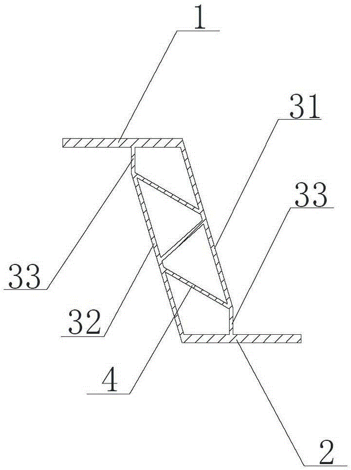
[0026] This embodiment is the most preferred for implementing the utility model. Such as figure 1 As shown, the photovoltaic module mounting frame for middle and low latitudes in this embodiment includes: an upper installation surface 1 and a lower installation surface 2, which are arranged parallel to each other; first main ribs 31 and second main ribs 32, which are arranged in parallel on Between the upper installation surface 1 and the lower installation surface 2, and form a Z-shaped structure with the upper installation surface 1 and the lower installation surface 2, the first main rib 31 and the second main rib 32 are also connected to the upper installation surface 1 and the lower installation surface respectively. 2 forms an included angle, the first main rib 31 forms an included angle of 105° with the upper mounting surface 1, and the second main rib 32 forms an included angle of 105° with the lower mounting surface 2; the three oblique ribs 4 are arranged obliquely i...

Embodiment 2

[0033] Others are the same as those described in Example 1, except that three main reinforcements are used, and multiple oblique reinforcements are arranged obliquely between every two main reinforcements, which can provide a stronger force bearing effect and are suitable for larger For the support of large-area photovoltaic modules, we can choose according to our own needs.

Embodiment 3

[0035] Others are the same as those described in Embodiment 1, except that: both ends of the main reinforcement can be provided with bending parts, which can make room for more components to be installed conveniently.


PUM


Abstract

The invention discloses a photovoltaic module installing rack for a low-and-medium-latitude zone. The photovoltaic module installing rack comprises an upper installing face, a lower installing face, at least two main ribs and a plurality of inclined ribs, wherein the upper installing face and the lower installing face are arranged in parallel, the main ribs are arranged between the upper installing face and the lower installing face in parallel, form a Z-shaped structure with the upper installing face and the lower installing face, and further form an included angle respectively with the upper installing face and the lower installing face, the included angles are 75-105 degrees, the inclined ribs are arranged between the at least two main ribs which are arranged in the inclined direction, and the upper installing face, the lower installing face, the main ribs and the inclined ribs are formed by aluminum alloy in an extruding mode. The photovoltaic module installing rack can guarantee economical efficiency, also can improve practicability and aesthetic property, and is suitable for the low-and-medium-latitude zone.

Description

technical field [0001] The invention relates to a photovoltaic module installation frame, in particular to a photovoltaic module installation frame used in middle and low latitude regions. Background technique [0002] Affected by the photovoltaic environment, large-scale photovoltaic power station projects have been expanding rapidly in the past two years, and competition among enterprises has intensified. Among them, the construction of photovoltaic power plants also needs to comprehensively consider the structural economy, practicality and aesthetics of the photovoltaic module mounting racks used. [0003] Most of the existing mounting frames are made of carbon steel. Since carbon steel has high hardness and strength, its plasticity is also low. The mounting frame made of this carbon steel is also limited to be made into a relatively regular shape, such as a rectangle or a simple bent shape, so this type of mounting frame can only play a simple supporting role for the ph...

Claims


Application Information

Patent Timeline
Patent Type & Authority Patents(China)
IPC IPC(8): H02S20/30H02S20/00
CPCY02E10/50
Inventor 王腾王柏兴强大梽孙利国李定宋卫杰
Owner 泗阳腾晖新能源技术有限公司
Why Eureka
Try Eureka