Bottom stop assembly of zipper fast to take off

A technology for stoppers and zippers, applied in the field of bottom stop components of quick-release zippers, which can solve the problems that the pivoting part 12 has a relatively large force, is easy to break, and is easy to break, and achieves the effects of convenient exit, reliable positioning, and short stroke

Active Publication Date: 2013-09-04
KEE (GUANGDONG) GARMENT ACCESSORIES LTD
View PDF7 Cites 4 Cited by
  • Summary
  • Abstract
  • Description
  • Claims
  • Application Information

AI Technical Summary

Problems solved by technology

The rear stop code of this structure, also known as the bottom stop assembly, although it can realize quick disengagement, its mating body 10 is only partially held in the groove 26 and slit 27 of its pivoting stop body 20 , and its pivoting part 12 has not been positioned and limited in the up and down direction, while its pivoting stop part 23 is hook-shaped and thus cantilever-shaped in fact, and is easy to break; the strength of the pivoting part 12 in the up and down direction will be There is a relatively large hidden danger, especially when this kind of zipper is used for high-intensity physical sports, the matching plate part 11 on the matching body 10 inserted into the groove 26 and the slit 27 is easy to break because it is too thin

Method used


Image

  • Bottom stop assembly of zipper fast to take off
  • Bottom stop assembly of zipper fast to take off
  • Bottom stop assembly of zipper fast to take off

Examples


Embodiment Construction

[0029] The specific embodiments of the present invention will be further described below in conjunction with the accompanying drawings.

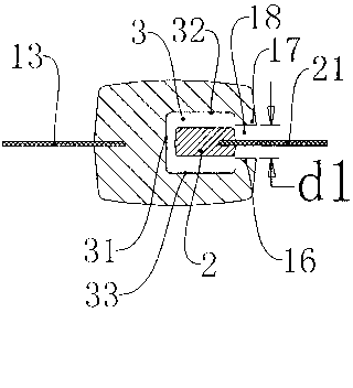
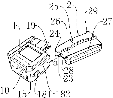
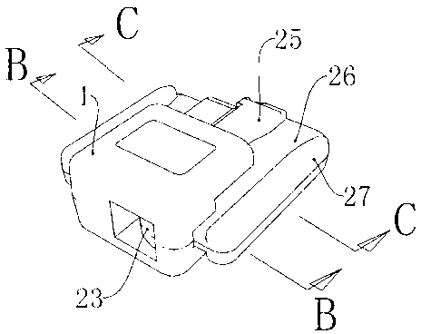
[0030] Such as figure 1 , figure 2As shown, a bottom stop assembly of a zipper includes a left stop 2 and a right stop 1, and the outer sides of the left stop 2 and the right stop 1 are respectively connected with a left zipper tape 21 and a right zipper tape 13, between which Connected by injection molding. The inner sides of the left zipper tape 21 and the right zipper tape 13 are respectively connected by injection molding to a left fastener element 22 and a right fastener element 12 which can be fastened to each other. When locking the zipper, first place the slider (not shown in the figure) on the tail end of the right stop 1, and then insert the left stop 2 into the right stop 1 after passing through the slider , then pull the slider to lock the left chain element 22 and the right chain tooth 12 together. It should be noted that t...


PUM


Abstract

A bottom stop assembly of a zipper comprises a left stop part and a right stop part, wherein the outer side of the left stop part and the outer side of the right stop part are connected with a left zipper chain and a right zipper chain respectively. A right inserting groove and an annular hole are formed in the inner side of the right stop part and extend in the inner side direction, the annular hole is located in the front end of the right inserting groove and is straightly communicated with a groove hole of the right inserting groove, and the left stop part can be movably inserted into the groove hole of the right inserting groove and can be taken off from the side edge port of the right inserting groove. When the left stop part is inserted into the groove hole of the right inserting groove, the top end portion of the left stop part can be inserted into the annular hole. As the left stop part can be inserted into the groove hole of the right inserting groove, the left stop part can be vertically positioned; as the left stop part can be taken off from the side edge port, when the left stop part is withdrawn from the right inserting groove, the left stop part can be driven by the left zipper chain to rotate around the outer side wall of the annular hole to be capable of rotating out, and withdrawing is very convenient and fast. The bottom stop assembly has the characteristics and the advantages, thereby being capable of being applied to bottom stop assemblies of zippers.

Description

technical field [0001] The invention relates to a bottom stop assembly of a quick-release zipper, in particular to a bottom stop assembly of a quick-release zipper that can effectively provide the locking function of the lower end of the zipper and provide the zipper to be disengaged quickly. Background technique [0002] It is a well-known technology that slide fasteners are used as fasteners for fabrics such as clothing. In order to apply a zipper to fabrics, it generally includes a bottom stop assembly. The bottom stop component is generally installed at the end of the zipper at the starting point of the slider, and its main function is to fasten the separated left and right zippers together before the slider starts, so as to facilitate the slider of the zipper to fasten the zipper. [0003] In the prior art, ZL200710141666.9 discloses "a zipper with a detachable end stop", which can be conveniently operated by everyone and is easy to close or separate. The zipper with a...

Claims


Application Information

Patent Timeline
Patent Type & Authority Applications(China)
IPC IPC(8): A44B19/24A44B19/38
CPCA44B19/38A44B19/388
Inventor 黄盛昌王涛
Owner KEE (GUANGDONG) GARMENT ACCESSORIES LTD
Why Eureka
Try Eureka