
Temperature-controlled shell body

A temperature control and housing technology, applied in the direction of manufacturing tools, auxiliary devices, auxiliary welding equipment, etc., can solve the problem of inability to effectively dissipate heat from the welding machine, and achieve the goal of preventing foreign matter from entering the interior of the air compressor, uniform cooling, and high heat dissipation efficiency Effect

Inactive Publication Date: 2015-02-18
中山市三联电器有限公司
View PDF8 Cites 0 Cited by
  • Summary
  • Abstract
  • Description
  • Claims
  • Application Information

AI Technical Summary

Problems solved by technology

[0005] The purpose of the present invention is to overcome the deficiency that the prior art cannot effectively dissipate heat from the welding machine, and provide a temperature control shell

Method used


Image

  • Temperature-controlled shell body
  • Temperature-controlled shell body
  • Temperature-controlled shell body

Examples


Embodiment Construction

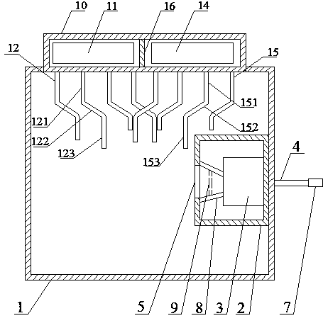
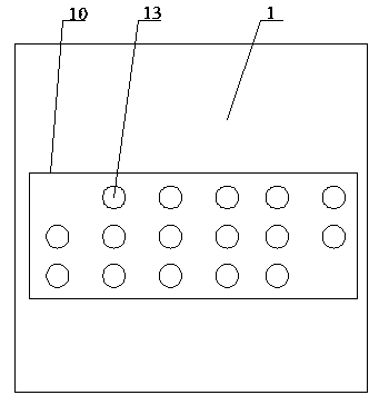
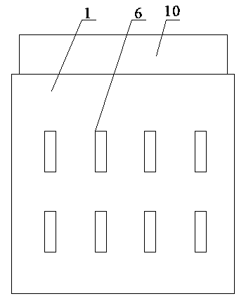
[0034] In order to enable those skilled in the art to better understand the present invention, the technical solutions in the embodiments of the present invention will be clearly and completely described below in conjunction with the drawings in the embodiments of the present invention. Obviously, the embodiments described below are only a part of the embodiments of the present invention, not all of them. Based on the embodiments described in the present invention, all other embodiments obtained by those skilled in the art without creative efforts are within the protection scope of the present invention.

[0035] Such as Figure 1~3 As shown, the temperature control housing includes a housing 1 with an open top, a box body 2, an air compressor 3, an air inlet pipe A4, an air outlet 5 and an exhaust grid 6, the box body 2 is fixed in the housing 1, and the air is compressed The machine 3 is fixed in the box body 2, the air inlet pipe A4 passes through the casing 1 and the box ...


PUM


Abstract

The invention discloses a temperature-controlled shell body. The temperature-controlled shell body comprises a shell body with the top opened, a box body, an air compressor, an air inlet tube A, an air outlet and an exhaust gate, wherein the box body is fixed inside the shell body, the air compressor is fixed inside the box body, the air inlet tube A penetrates through the shell body and the box body and is connected with the inlet of the air compressor, the air outlet is formed in the shell body, the air outlet right faces the outlet of the air compressor, and the exhaust gate is arranged on the shell body and right faces the air outlet. The temperature-controlled shell body further comprises a cover body, a first fan and a plurality of exhaust tubes, wherein the cover body is arranged on the top of the shell body, the first fan is arranged inside the cover body, the exhaust tubes are arranged on the bottom of the cover body and are communicated with the internal space of the cover body, the positions where the exhaust tubes are connected with the cover body are located within the range of the first fan, and air holes are formed in the top of the cover body. The temperature-controlled shell body has the advantages that active radiating is achieved and the radiating performance is good.

Description

technical field [0001] The invention relates to the field of welding equipment, in particular to a temperature control shell. Background technique [0002] The welding machine will generate high temperature and high heat during operation. If the generated heat cannot be dissipated in time, it will seriously affect the normal operation of the equipment, and even bring safety hazards. Therefore, it is necessary to dissipate heat from the welding machine. [0003] Existing welding machines realize the natural dissipation of heat therein by opening holes in the welding machine casing. However, this heat dissipation method is inefficient, and the heat generated by the welding machine cannot be dissipated at all when the welding machine is working at a high intensity. [0004] Now, there is an urgent need in this field for a device that can actively and efficiently take away the heat generated during the welding machine's work. Contents of the invention [0005] The purpose o...

Claims


Application Information

Patent Timeline
Patent Type & Authority Patents(China)
IPC IPC(8): B23K37/00
Inventor 王曾勇叶礼
Owner 中山市三联电器有限公司
Learn More