
Electric automatic differential lock

A differential lock, electric technology, applied in the field of automobile drive train, can solve problems such as difficult to grasp and use flexibly, cumbersome, loss of differential, etc., and achieve the effect of easy promotion and use, convenient operation and good use effect

Inactive Publication Date: 2013-09-04
优必胜(福建)机械工业有限公司
View PDF6 Cites 4 Cited by
  • Summary
  • Abstract
  • Description
  • Claims
  • Application Information

AI Technical Summary

Problems solved by technology

[0002] The differential is mainly used to balance the speed difference between the inner and outer wheels when the vehicle is turning, so that the vehicle can turn smoothly without consuming too much energy. It is precisely because of the differential principle of the differential and the effect of equal torque that when the vehicle is driving In bad road conditions, the wheels often fall into the mud, sand or ice and snow roads, causing a wheel to slip or even hang in the air, so that the vehicle is trapped and unable to extricate itself. In this case, the driver usually thinks of padding under the slipping wheel Hard objects such as stones to increase the adhesion of the wheels, but this method is often self-defeating, making the wheels sink deeper and deeper
[0003] At present, the solution for some off-road vehicles and high-end SUVs is to use a differential lock to lock the differential, so that the differential will lose its function, so that the main reducer can evenly distribute the speed of the left and right half shafts, so that more power can be distributed to the future. When the slipping wheel goes up, it can be seen that the function of the differential lock is to ensure that the other wheel can obtain sufficient driving force when one wheel slips. However, the existing mechanical differential lock mechanism is complex, difficult to maintain, and has a high failure rate. High, the operation is cumbersome for ordinary drivers, and it is difficult to master and use flexibly

Method used


Image

  • Electric automatic differential lock

Examples


Embodiment 1

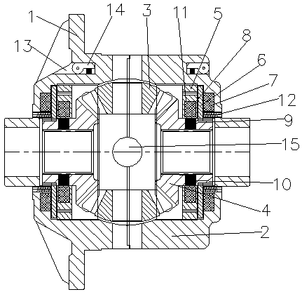
[0016] refer to figure 1 As shown, the electric automatic differential lock includes a large differential lock case 1, a small differential lock case 2 set on one end of the large differential lock case 1, and a small differential lock case 2 installed on the large differential lock case 1 and the small differential lock case 2. Between the planetary gear 3 fixed by the cross shaft 15, a side gear 4 is respectively arranged in the large differential lock case 1 and the small case 2 of the differential lock, and each side gear 4 meshes with the planetary gear 3 respectively. The gear 4 is provided with a plurality of alternator permanent magnets 9 with positive and negative poles arranged alternately, the side gear 4 is covered with a generator iron core 5 and a generator coil 8, and the differential lock shells 1 and 2 are equipped with an electromagnet coil 7 And the friction plate 6, the friction plate 6 is arranged between the generator iron core 5 and the electromagnet coi...


PUM


Abstract

The invention discloses an electric automatic differential lock comprising a differential lock large shell, a differential lock small shell nested at one end of the differential lock large shell, and a planet gear. The planet gear mounted between the differential lock large shell and the differential lock small shell is fixed through a cross shaft. Each of the differential lock large shell and the differential lock small shell is provided with an axle shaft gear inside. Both the axle shaft gears mesh with the planet gear. Each axle shaft gear is provided with a plurality of generator permanent magnets with alternately arranged positive and negative poles inside. A generator core and a generator coil are sleeved outside the axle shaft gears. An electromagnet coil and a friction plate are disposed in each of the differential lock large shell and the differential lock small shell. Regulating springs and screws are disposed between each electromagnet coil and one of the differential lock large shell and the differential lock small shell. Each of the differential lock large shell and the differential lock small shell is provided with a speed-limiting eccentric switch. Through the structure, the problem that an automobile idles due to skidding of a single wheel is solved, and the automobile can be freed of the dangerous situation and driven normally. The electric automatic differential lock has the advantages of simple structure, convenience in use and operation, low failure rate, high stability and convenience in popularization.

Description

technical field [0001] The invention relates to the field of automobile drive trains, in particular to an electric automatic differential lock for automobiles. Background technique [0002] The differential is mainly used to balance the speed difference between the inner and outer wheels when the vehicle is turning, so that the vehicle can turn smoothly without consuming too much energy. It is precisely because of the differential principle of the differential and the effect of equal torque that when the vehicle is driving In bad road conditions, the wheels often fall into the mud, sand or ice and snow roads, causing a wheel to slip or even hang in the air, so that the vehicle is trapped and unable to extricate itself. In this case, the driver usually thinks of padding under the slipping wheel Hard objects such as stones to increase the adhesion of the wheels, but this method is often self-defeating, making the wheels sink deeper and deeper. [0003] At present, the solutio...

Claims


Application Information

Patent Timeline
IPC IPC(8): F16H48/34
Inventor 洪祖煜
Owner 优必胜(福建)机械工业有限公司
Learn More