Pipeline type welding machine cooler

A cooler and welding machine technology, applied in the direction of heat exchanger types, indirect heat exchangers, fixed conduit components, etc., can solve the problem that the welding machine cannot effectively dissipate heat, and achieve material saving, good thermal conductivity, and good heat dissipation performance. Effect

Inactive Publication Date: 2013-09-04
四川东方能源科技股份有限公司
View PDF6 Cites 3 Cited by
  • Summary
  • Abstract
  • Description
  • Claims
  • Application Information

AI Technical Summary

Problems solved by technology

[0005] The purpose of the present invention is to overcome the deficiency that the prior art cannot effectively dissipate heat to the welding machine, and to provide a pipeline type welding machine cooler

Method used


Image

  • Pipeline type welding machine cooler
  • Pipeline type welding machine cooler
  • Pipeline type welding machine cooler

Examples


Embodiment 1

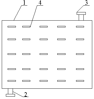
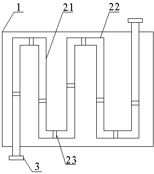
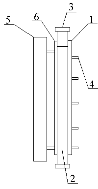
[0029] Such as Figure 1~Figure 3 As shown, the pipe-type welder cooler includes a side plate 1, a serpentine air duct 2 and a fan 3, the serpentine air duct 2 is arranged inside the side plate 1, and the two ends of the serpentine air duct 2 protrude from the side plate 1 respectively. The upper and lower ends of the upper and lower ends of the serpentine air duct 2 are provided with fans 3;

[0030] In use, this embodiment is used to form the side wall of the welding machine housing. A fan 3 sends external cold air into the serpentine air duct 2, and the cold air absorbs the heat emitted by the welding machine in the serpentine air duct 2, and the air that has absorbed the heat is discharged through another fan 3 again. Radiating fins 4 dissipate part of the heat of the air in the serpentine air duct 2 . Through the serpentine air duct 2, the fan 3 and the heat sink 4, this embodiment realizes active heat dissipation and has good heat dissipation performance.

[0031] In ...


PUM


Abstract

The invention discloses a pipeline type welding machine cooler which comprises a side plate, an S-shaped air duct and fans, wherein the S-shaped air duct is arranged inside the side plate, the two ends of the S-shaped air duct extend out of the upper end of the side plate and the lower end of the side plate respectively, and the fans are arranged at the two ends of the S-shaped air duct respectively. The pipeline type welding machine cooler further comprises heat dissipation pieces which are arranged outside the side plate. The pipeline type welding machine cooler has the advantages of achieving initiative heat dissipation and being good in heat dissipation performance due to the fact that the S-shaped air duct, the fans and the heat dissipation pieces are arranged.

Description

technical field [0001] The invention relates to the field of welding equipment, in particular to a pipeline type welder cooler. Background technique [0002] The welding machine will generate high temperature and high heat during operation. If the generated heat cannot be dissipated in time, it will seriously affect the normal operation of the equipment, and even bring safety hazards. Therefore, it is necessary to dissipate heat from the welding machine. [0003] Existing welding machines realize the natural dissipation of heat therein by opening holes in the welding machine casing. However, this heat dissipation method is inefficient, and the heat generated by the welding machine cannot be dissipated at all when the welding machine is working at a high intensity. [0004] Now, there is an urgent need in this field for a device that can actively and efficiently take away the heat generated during the welding machine's work. Contents of the invention [0005] The purpose...

Claims


Application Information

Patent Timeline
Patent Type & Authority Applications(China)
IPC IPC(8): F28D1/047
Inventor 王曾勇叶礼
Owner 四川东方能源科技股份有限公司
Why Eureka
Try Eureka