Static mixer
A technology of static mixers and mixers, applied in the direction of fluid mixers, mixers, chemical instruments and methods, etc., can solve the problems of high fin processing requirements, large fin flow resistance, and inconvenient manufacturing, so as to ensure mixing Effect and pipeline, enhanced turbulence, low cost effect
Inactive Publication Date: 2013-09-11
扬州清溢环保科技有限公司 +1
View PDF0 Cites 8 Cited by
- Summary
- Abstract
- Description
- Claims
- Application Information
AI Technical Summary
Problems solved by technology
[0002] At present, the static mixer has the disadvantages of complex structure, high flow resistance caused by large fin angle, high fin processing requirements, inconvenient manufacturing, large resistance drop, dead angle, and high energy consumption.
Method used
View moreImage
Smart ImageViewing Examples
Examples
Embodiment Construction
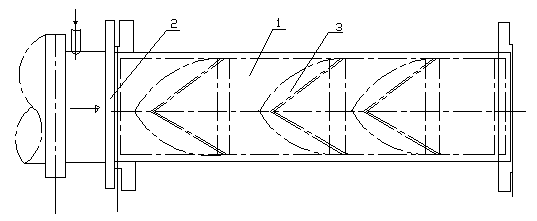
[0008] Static mixer, the main body of the mixer is a circular tube 1, a plurality of mixer units 3 are sequentially arranged in the circular tube 1 in the water inlet direction, and a filter grid is provided at the water inlet of the circular tube 1 Grid 2.
Login to View More PUM
 Abstract
The invention relates to a static mixer. A main body of the static mixer is a circular pipe; a plurality of mixer units are arranged sequentially in the circular pipe in the water inlet direction; a filtering barrier is arranged in a water inlet of the circular pipe. According to the static mixer, the cylindrical circular pipe is adopted as a pipeline and a flow guide element, so that the structure is simple, the manufacture is convenient, and the cost is low; in addition, the high flow flux is realized on the premise that the pipeline is small in size; the static mixer is provided with the plurality of mixer units, so that flowing dead corner is avoided, the radial difference of the liquid states is effectively removed, the turbulence motion of liquid flowing through the static mixer is improved, the uniformity of mixing is ensured, and a boundary layer is thinned, thus being beneficial for heat transfer and mass transfer; the barrier with the filtering performance is arranged in the water inlet, so that the mixing effect and the smoothness of the pipeline can be ensured.
Description
technical field [0001] The invention relates to a fluid mixing device, in particular to a static mixer. Background technique [0002] At present, static mixers have the disadvantages of complex structure, large flow resistance caused by large fin angles, high fin processing requirements, inconvenient manufacturing, large resistance drop, dead angle, and high energy consumption. Therefore, the existing technology needs to be improved and perfected to design a new type of static mixer with more industrial application value. Contents of the invention [0003] In order to solve the above problems, the present invention provides a static mixer with simple structure, no power source, uniform mixing and unobstructed pipeline. [0004] The technical solution of the present invention is: the main body of the mixer is a round tube, and a plurality of mixer units are sequentially arranged in the water inlet direction in the round tube, and a filter grill is arranged at the water inl...
Claims
Login to View More Application Information
Patent Timeline
 Patent Type & Authority Applications(China)
IPC IPC(8): B01F5/06
Inventor 谈家彬夏四清吴静吴军王凤云黄伟航石延松王春兵戴家将潘伟
Owner 扬州清溢环保科技有限公司
Features
- R&D
- Intellectual Property
- Life Sciences
- Materials
- Tech Scout
- Unparalleled Data Quality
- Higher Quality Content
- 60% Fewer Hallucinations
Learn More Browse by: Latest US Patents, China's latest patents, Technical Efficacy Thesaurus, Application Domain, Technology Topic, Popular Technical Reports.
© 2025 PatSnap. All rights reserved.Legal|Privacy policy|Modern Slavery Act Transparency Statement|Sitemap|About US| Contact US: help@patsnap.com

