Tube bending and forming mechanism

A forming mechanism and pipe bending technology, applied in the field of pipe bending forming mechanism, can solve problems such as low production efficiency, failure to meet large-scale production needs, lack of continuity in processing, etc., and achieve continuous production and smooth production efficiency.

Inactive Publication Date: 2013-09-11
JIANGSU YONGLONG ELECTRIC
View PDF0 Cites 3 Cited by
  • Summary
  • Abstract
  • Description
  • Claims
  • Application Information

AI Technical Summary

Problems solved by technology

[0004] The 360° pipe bending machine provided by the above patent application can only form one round tube at a time. After the round tube is formed, the tube must be broken before the next round tube can be formed. The processing lacks continuity and the production efficiency is low, so it cannot meet the needs of large-scale production. The production demand needs to be further improved

Method used


Image

  • Tube bending and forming mechanism
  • Tube bending and forming mechanism
  • Tube bending and forming mechanism

Examples


Embodiment Construction

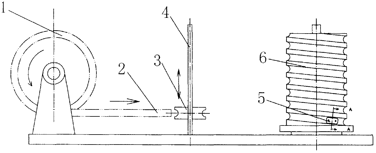
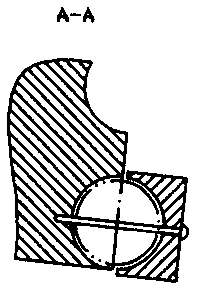
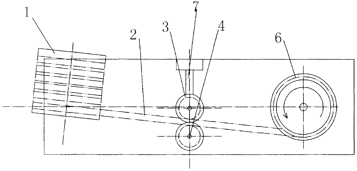
[0018] The present invention includes a frame, a pipe delivery mechanism and a pipe bending mechanism 6 arranged on the frame; wherein the pipe delivery mechanism 6 includes a delivery mechanism 1 and a pipe discharge mechanism arranged between the delivery mechanism 1 and the bending mechanism 6, The pipe release mechanism includes a shaft 4 vertically arranged on the frame, and a roller 3 that can move up and down along the shaft 4 is sleeved on the shaft 4. The roller 3 is provided with an annular concave surface that cooperates with the tube blank 2; The mechanism 6 includes a rotating cylinder, the outer circumference of which is processed into a spiral groove corresponding to the tube blank 2, the lower end of the bending mechanism 6 is provided with a clamp 5 for fixing the end of the tube blank 2; the roller 3 is on the shaft 4 The speed of movement corresponds to the rotational speed of the cylinder.

[0019] The pipe releasing mechanism of the present invention is pr...


PUM


Abstract

The invention relates to a tube bending and forming mechanism which comprises a tube discharging mechanism and a tube bending mechanism, wherein the tube discharging mechanism comprises a shaft, the shaft is sleeved with roller wheels which can move along the shaft vertically, and annular concaved surfaces matched with a tube blank are formed in the roller wheels; the tube bending mechanism comprises a rotating cylinder, an outer circle of the cylinder is processed to be a spiral groove corresponding to the tube blank, and a clamp for fixing the end part of the tube blank is arranged at the lower end of the tube bending mechanism; and the moving speeds of the roller wheels on the shaft correspond to a rotating speed of the cylinder. According to the tube bending and forming mechanism, by means of effective matching of the tube discharging mechanism and the tube bending mechanism, compared with a conventional tube bending mechanism, continuous production is realized; and in order to realize smooth and fast production, the tube discharging mechanism can be inclined at a certain angle, so that tubes can be smoothly discharged.

Description

technical field [0001] The invention relates to a bending pipe forming mechanism, specifically, it is applied to forming a circular pipe such as a pressure equalizing ring from a straight pipe. Background technique [0002] In many occasions, it is necessary to use large-diameter pipe circles, such as anti-halo rings on power lines. Traditional anti-halation rings are generally welded by multiple arc circles, which makes the overall dimensional accuracy poor and affects the anti-halation effect. In addition, this anti-halation ring is complicated to manufacture and requires multiple welds. [0003] For this reason, the patent application number 2009100284318 provides a 360 ° pipe bender, which bends the pipe end when the straight pipe is fed, so that the straight pipe is plastically deformed according to the set center and radius. In order to bend the pipe into a complete 360°, the pinch roller group, guide roller 1, and guide roller 2 are respectively inclined to form a s...

Claims


Application Information

Patent Timeline
Patent Type & Authority Applications(China)
IPC IPC(8): B21D11/06B21D11/22
Inventor 张道勇
Owner JIANGSU YONGLONG ELECTRIC
Why Eureka
Try Eureka