
Automatic conveying device

A transmission device and automatic technology, applied in the direction of conveyor control devices, transportation and packaging, conveyor objects, etc., can solve the problems of falls, low transportation efficiency, smashing injuries, etc., to reduce energy waste, reduce labor intensity, The effect of prolonging the service life

Active Publication Date: 2013-09-11
长城汽车股份有限公司平湖分公司
View PDF6 Cites 19 Cited by
  • Summary
  • Abstract
  • Description
  • Claims
  • Application Information

AI Technical Summary

Problems solved by technology

[0002] In the process of industrial production, it is often necessary to transport materials from one station to another. There are mainly two methods of material transportation: manual transportation and conveyor belt transportation. The disadvantages of manual transportation are low transportation efficiency and high labor intensity for workers, especially When it is necessary to go up or down the stairs, there is still a risk of falling and smashing during transportation
Although the conveyor belt conveying method can overcome the above shortcomings, the existing conveyor belts generally can only run continuously, and cannot automatically adjust the operating state according to the material conveying rhythm. Waste of energy, but also shorten the service life of the conveyor belt, thereby increasing the cost of material transportation

Method used


Image

  • Automatic conveying device
  • Automatic conveying device

Examples


Embodiment Construction

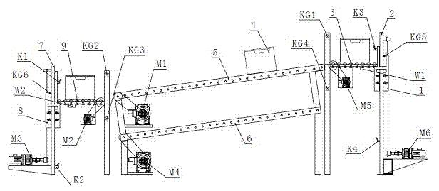
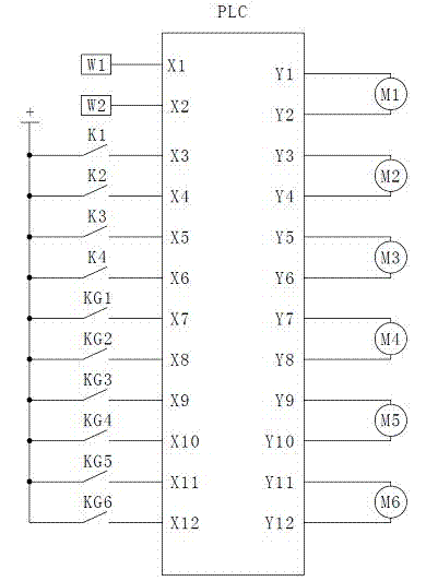
[0014] see figure 1 , figure 2 , the present invention includes item box 4, feeding elevator (including lifting table 1 of feeding elevator, vertical slideway 2 of feeding elevator, feeding roller 3, feeding motor M5, lifting drive motor M6 of feeding elevator), receiving elevator (including receiving elevator) Material elevator vertical slideway 7, lifting table 8 of material receiving elevator, material receiving roller 9, material receiving motor M2, lifting drive motor M3 of material receiving elevator), upper conveyor belt 5, lower conveyor belt 6 and intelligent control system. Its working process is as follows:

[0015] Load the material to be conveyed into the item box 4 located on the upper part of the feeding elevator. When the weight of the item box 4 reaches or exceeds the set value, the first gravity sensor W1 sends the corresponding electrical signal to the PLC, and the PLC collects the signal. Start the feeding motor M5, and the feeding motor M5 drives the fe...


PUM


Abstract

An automatic conveying device comprises a goods box, a feeding lifter located at the feeding station, a collecting lifter located at the collecting station, an upper conveying belt, a lower conveying belt and an intelligent control system, wherein the two ends of the upper conveying belt and the two ends of the lower conveying belt are connected with the feeding lifter and the collecting lifer respectively, the upper conveying belt is located below the lower conveying belt, a feeding idler wheel is arranged on the upper portion of the lifting platform of the feeding lifter, a feeding motor is arranged on the lower portion of the lifting platform of the feeding lifter and drives the feeding idler wheel through a transmission device, a collecting idler wheel is arranged on the upper portion of the lifting platform of the collecting lifter, and a collecting motor is arranged on the lower portion of the lifting platform of the collecting lifter and drives the collecting idler wheel through a transmission device. The automatic conveying device can control the running states of the two conveying belts according to the weight of material containing in the goods box, starting and stopping in good time of the conveying device are achieved, while labor intensity of workers is reduced, wasting of energy resources is effectively reduced, accident hidden danger is eliminated, and the service life of the conveying device is prolonged.

Description

technical field [0001] The invention relates to a conveyor belt used for conveying articles between two stations, belonging to the technical field of conveying. Background technique [0002] In the process of industrial production, it is often necessary to transport materials from one station to another. There are mainly two methods of material transportation: manual transportation and conveyor belt transportation. The disadvantages of manual transportation are low transportation efficiency and high labor intensity for workers, especially When it is necessary to go up or down stairs, there is still a risk of falling and crushing injuries during the transportation process. Although the conveyor belt conveying method can overcome the above shortcomings, the existing conveyor belts generally can only run continuously, and cannot automatically adjust the operating state according to the material conveying rhythm. Waste of energy, but also shorten the service life of the conveyo...

Claims


Application Information

Patent Timeline
IPC IPC(8): B65G43/08
Inventor 刘超谭小亮石志强王旭王云飞贾树利
Owner 长城汽车股份有限公司平湖分公司
Learn More